
A Nixie clock
a vintage way to tell the time
Introduction
Nixie tubes have been put on the market in the mid 1950's by Burroughs. They are neon discharge tubes where there is a common anode and several cathodes. The latter are shaped following the numbers one wants to represents. By applying a sufficient voltage between the anode and one of the cathodes, the selected cathode glows thanks to a yellow/orange-ish electrical discharge in the gas.
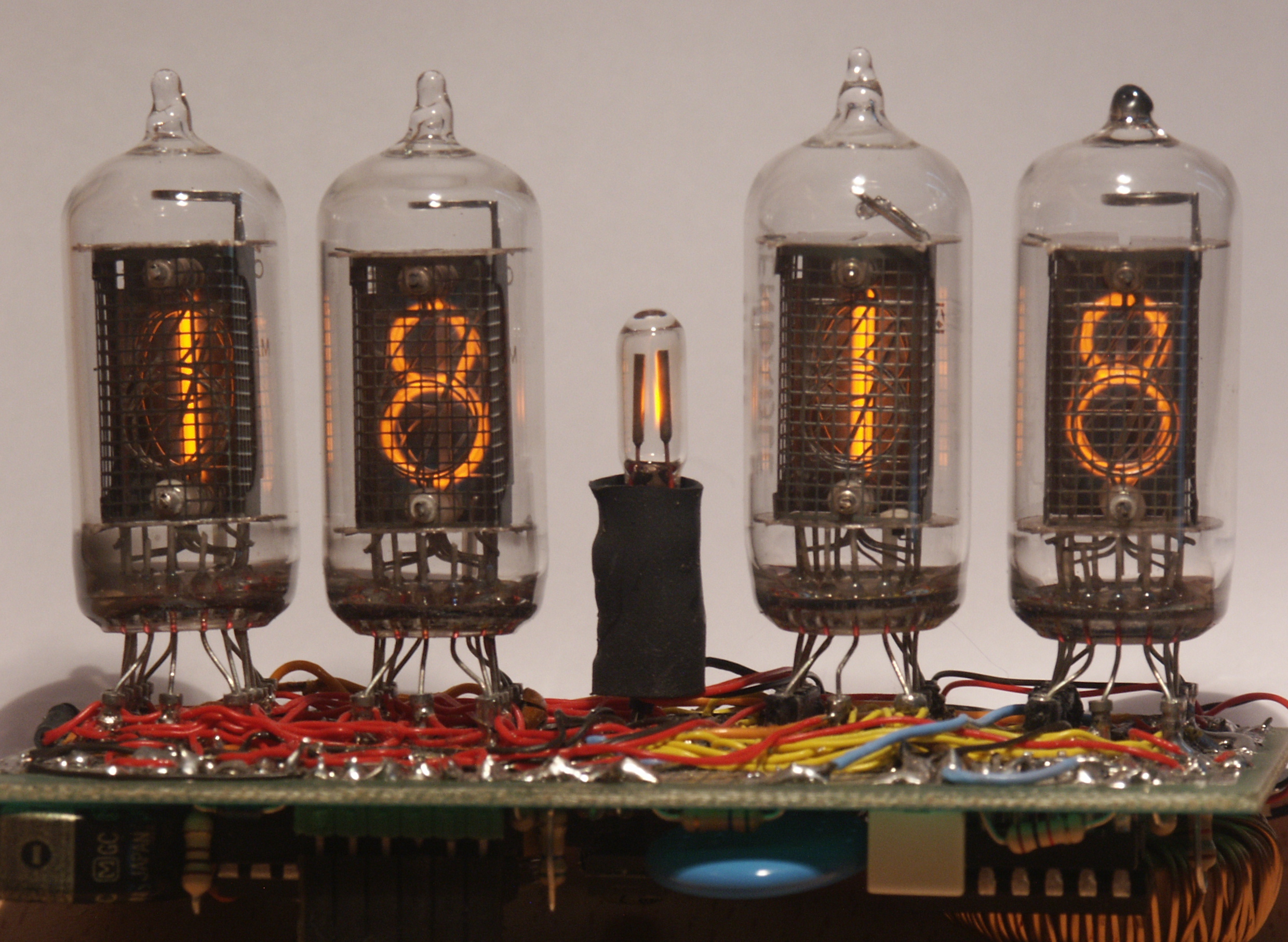
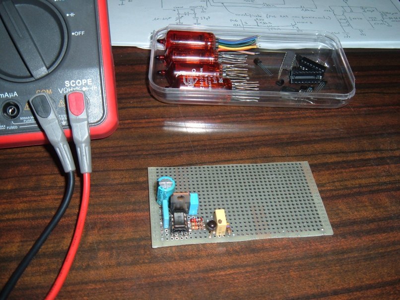
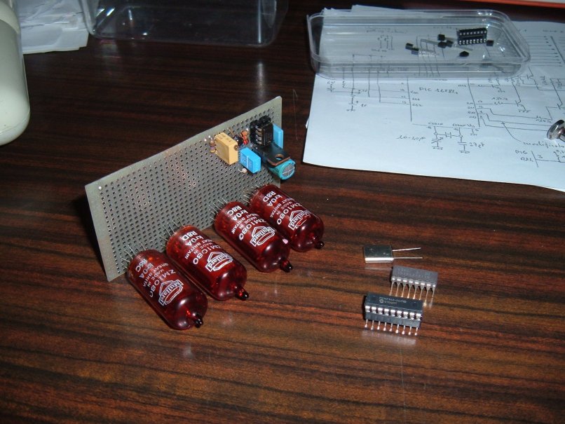
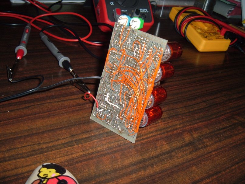
Tearing apart an old broken multimeter, I got in my hands some of those tubes (the exact model was TAF1317A) and with a friend we tried to find a way to use them. Browsing the Internet, a lot of information about those display is available, since they have a definite vintage charm. We thus decided to build a clock using those tubes. To keep everything as simple as possible, I decided to use a microcontroller and in particular the good old PIC16F84A. It is obsolete, but it is easy to found one of those laying in the junk box (at least, this was my case, it would not be very difficult to adapt everything to a newer microcontroller).
In the same multimeter where I found the Nixie tubes, I also found several 7441 drivers, which allows to obtain a simple circuit. If you like this project, you might read also A nixie clock, version 2.1 on my site. Several defects of the first prototypes have been corrected and a printed circuit board is available.
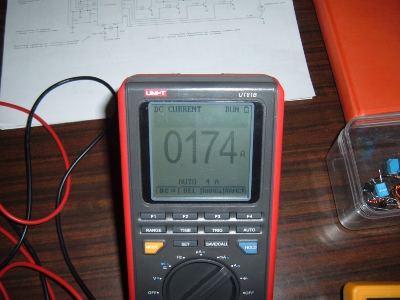
Inside the circuit, there is a simple voltage converter able to obtain the 170 V indispensable for powering the Nixie tubes, from a low voltage (6 ) stabilized supply. This choice is motivated by the need of obtain a rather safe circuit and without a special transformer. Some realizations you might find on the Internet suggest to obtain the 170 V directly by rectifying the 110 V AC mains (in the United States). This is for me a very dangerous idea and I suggest not to use this solution. However, it is clear that even if the current provided by the converter is small, this circuit is not for beginners: 170 V can bite very hard! Moreover, the circuit presented in this page is not fool proof. The overall power consumption is around 250 mA.

The circuit
This circuit is quite simple, since all the complicated stuff is done by the PIC16F84 microcontroller. In particular, it handles in the same time the hour calculation and the multiplexing of the Nixie tubes. Here is the first version of the circuit:
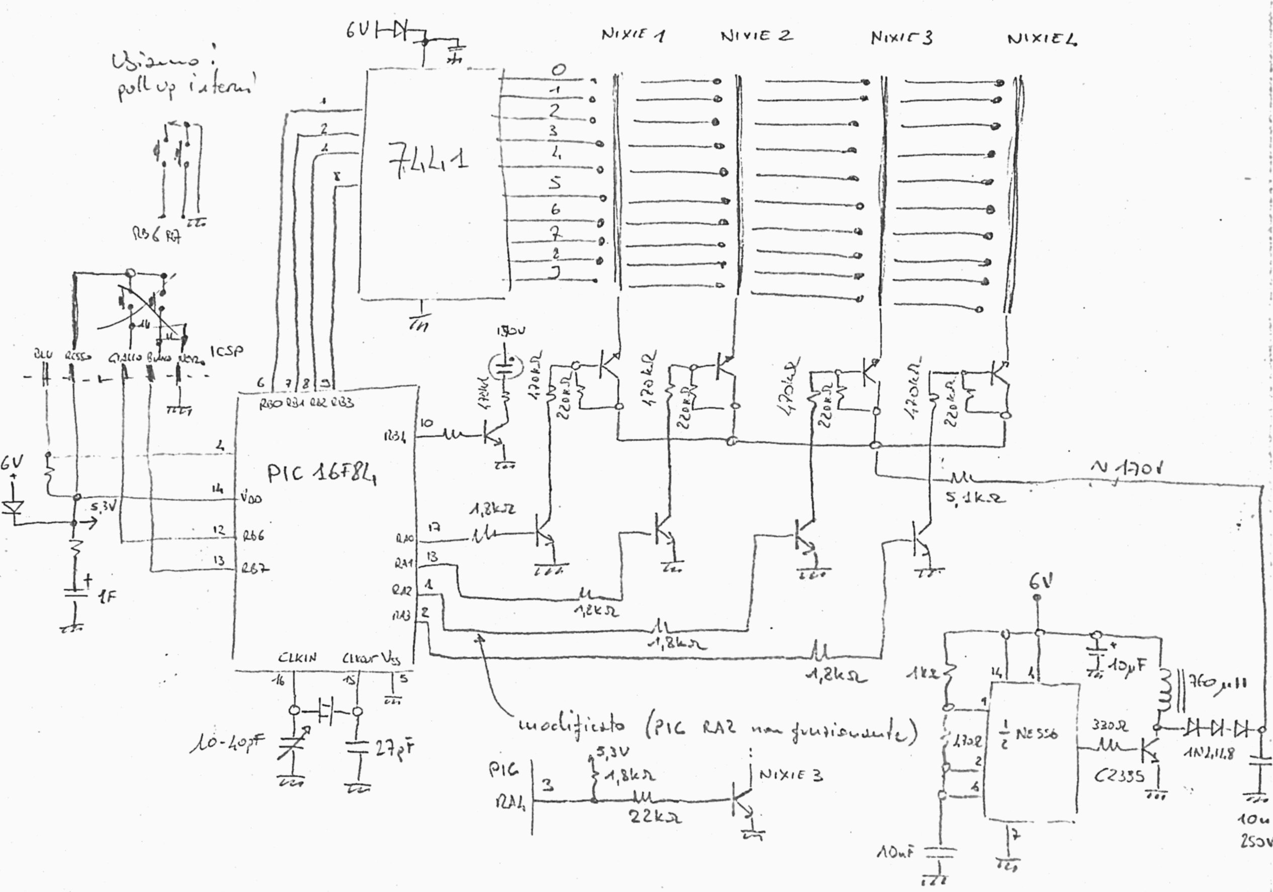
A rectangular wave oscillator, obtained with half of a common NE556 (in reality, a NE555 would have been enough), is used in a basic step-up circuit. The output signal of the oscillator controls a power transistor which acts on an inductor. Even if the output current is always below 5 mA, it is very important that the diode used is sufficiently fast and bale to handle the voltages around it. A standard rectifier diode is done for rectifying 50 Hz and would not work here, where the frequency is much higher. A simple hack I adopted is to use three common 1N4148 diodes in series, to obtain a very fast diode, able to handle the currents needed. I used for the inductor a small toroidal inductor taken from an anti-EMI filter. It is definitively possible to find something much better.
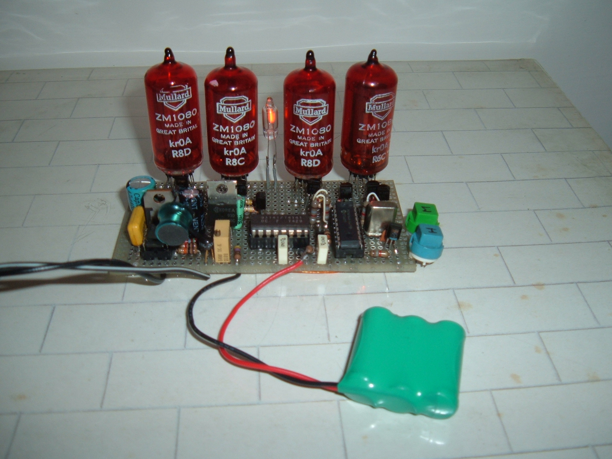
The microcontroller controls the Nixie tubes using multiplexing and the 7441 driver. Eight NPN transistors are used to handle the signals to be applied to the anodes of the four tubes. The main task of the software is to light up a Nixie tube at once, while putting the BCD code of the number to be shown on the lines controlling the 7441. My advice is to use eight transistors able to handle at least 200 V between emitter and collector. In reality, the 470 kΩ and 220 kΩ resistances makes this circuit more tolerant against some poor performance transistor. In fact, in the first prototype I used some prehistoric 2N1990 (obsoleted at least thirty years ago), which however work as expected. The PIC microcontroller clock is at 2.2768 MHz. This particular value has been chosen because it is easy to obtain a reference signal of 1 Hz with some simple divisions in the microcontroller prescaler and firmware.
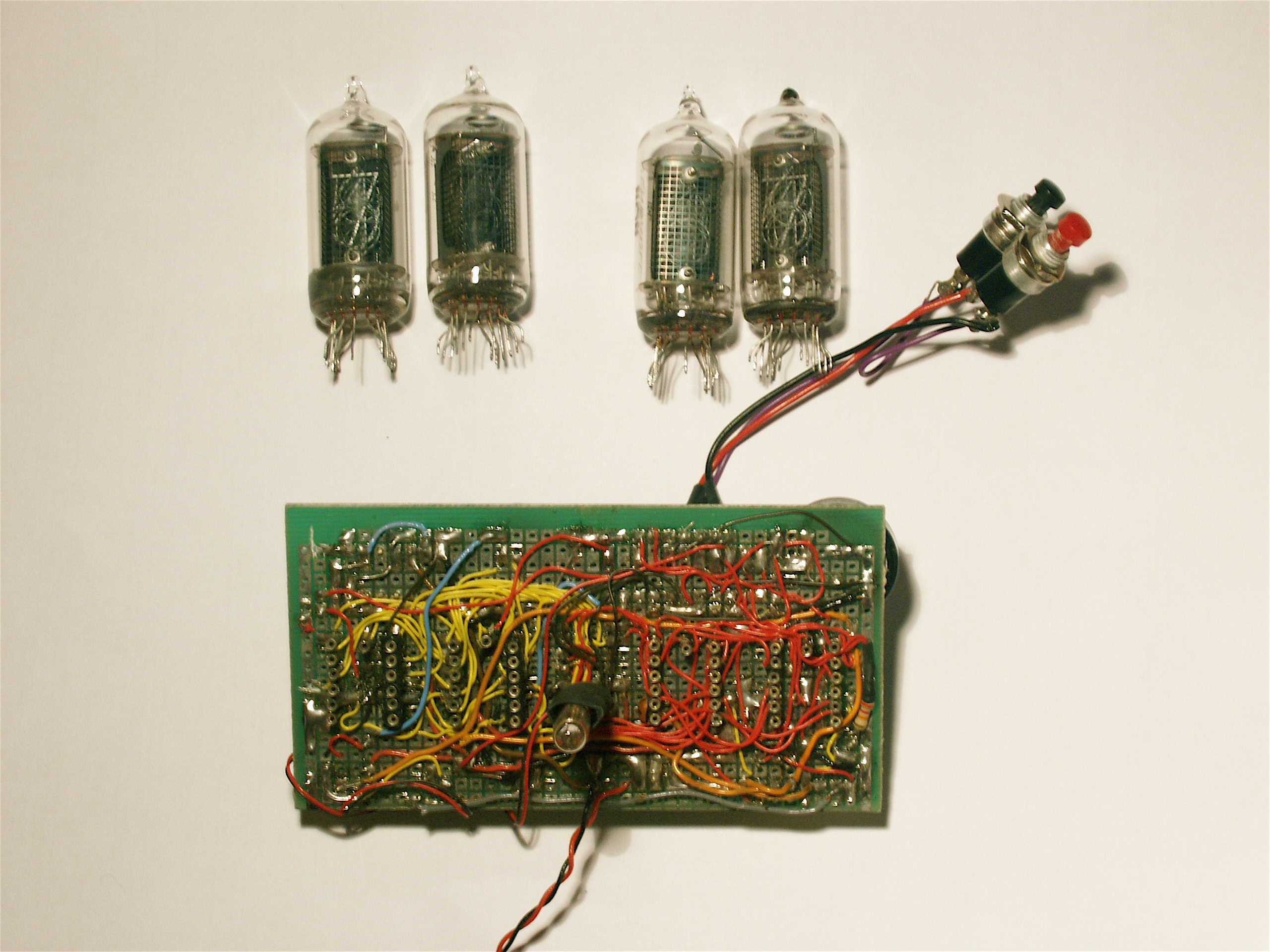
The microcontroller power supply is done via a diode and a 6 V line. This configuration has been adapted to allow for the in circuit programming of the PIC thanks to the ICSP (In Circuit Serial Programming) connector. The diode avoids that the programmer has to power up the whole circuit. Moreover, a 1 F capacitor (yes, one farad) is charged thanks to a 100 Ω resistor and it is used to power up the microcontroller for a few tens of minutes. Capacitor such as this one were easy to be found on old computer motherboards.
The ICSP connector is also exploited to connect two buttons to the RB6 and RB7 lines, that allow (thanks to the software-activated pull-up resistances internal to the PIC) to adjust the hours and the minutes to obtain the correct time.
In a first time, I considered using RA0, RA1, RA2 e RA3 for the Nixie tube multiplexing control. In my prototype, I used a PIC16F84 which survived a little incident and the RA2 line was not working. I therefore used the open drain RA4 line. I used a pull-up resistance and a simple change in the firmware, in the activatedisplay routine. What you find in the source files I publish is however configured to use RA2.
Francesco Nardi's circuit
Probably the first critics which can be done to the DC-DC converter is the fact that in my prototype the feedback is missing. The output voltage depends on the fact that the Nixie tube require more or less a constant current and that the input voltage is stabilized to 6 V with a LM317 regulator. Using some feedback would allow to power up the converter before the regulator, with a non stabilized voltage, thus increasing the overall efficiency. Moreover, in my prototype I selected the component values which allowed me to obtain more or less the wanted voltage. Tolerances or dispersion in the values would make sort that the obtained voltage is too low for lightning up the Nixie tubes.
Francesco Nardi has fabricated a version of my circuit, using a better DC-DC converter.Here is the schematics of Francesco's clock. I think it is a more refined version of the circuit, so if you want to fabricate it is a better choice than the one of my prototype:
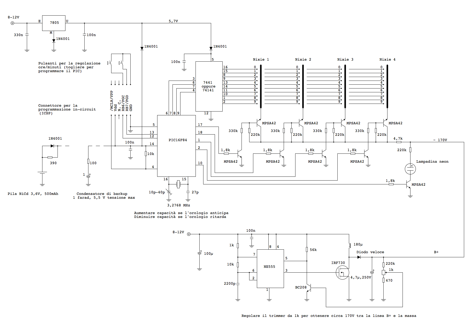
In the Francesco's circuit, the DC-DC converter has been improved with a feedback which allows to keep the output voltage around 170 V. Moreover, Francesco has used a 3,6 V NiCd battery which allows to power up the circuit for several hours in the case of a blackout. In the circuit, I indicated both the battery and the capacitor. The orologio_nixie_2_0.fcd file contains the schematics drawn with the FidoCadJ software, an open source project described in this same web site.
The firmware
The firmware is quite simple and all it has to do is:
- handle the Nixie tube multiplexing
- calculate the increment of the seconds, minutes and hour counters from the system clock
- keep the updated minutes and hours indication on the tubes
- handle a simple user interface to let the user adjust the clock with two buttons
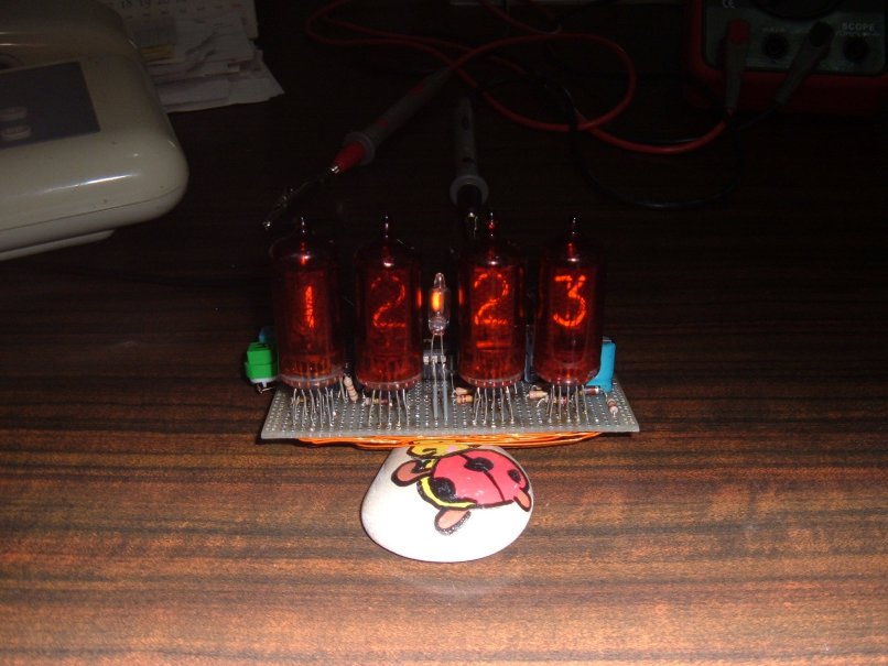
The first three operations are handled via an interrupt handler, which is automatically called thanks to the internal prescaler at a 200 frequency. Each time the handler is called, it refreshes the Nixie tubes and updates the counters. If the refresh frequency is high enough, the persistence of vision will give the impression that every Nixie tube is light at the same time. In our circuit, the overall refresh frequency is 50 Hz. I adopted the very same technique (with a slightly different circuit) in the Clock with PIC16F84 and PCF8573 article.
The two buttons are checked during the main loop. It tries to understand if the buttons are pressed, avoid the bounces and advance the hours and minutes counters.
Download here the assembly firmware source file, to be compiled (with gpasm, for example) and programmed on the PIC. And if you are lazy, here is the compiled HEX file, ready to be uploaded: NixieClock.hex
Other realizations
Francesco sent to me some photos of his circuit, which I publish there with a lot of pleasure.
Alex has exploited the first photo of this article to create a virtual clock made in Flash. Here is his page: http://www.alexoleron.com/alexoleron_services/horlogenixie.php
Conclusion
This small circuit has been fabricated using more or less only savaged components. This means that some choices are not the best possible ones. For example, using an inductor made with a better core material (number 26 is too lossy) would increase the circuit efficienty. Moreover, it would be advantageous to adopt a MOSFET instead of a bipolar circuit in the converter and of course applying a closed loop control. Francesco obtained some good results correcting those points. A second point concerns the microcontroller: the PIC16F84 is now obsolete and if it can still be found, better and cheaper alternatives exist. I believe that all the code might be easily adapted to a PIC16F628 with only minor modifications.
--------

    Copyright (C) 2007-2008  Davide Bucci     davbucciPleasenospamherE@tiscali.it

    This program is free software; you can redistribute it and/or modify
    it under the terms of the GNU General Public License as published by
    the Free Software Foundation; either version 2 of the License, or
    (at your option) any later version.

    This program is distributed in the hope that it will be useful,
    but WITHOUT ANY WARRANTY; without even the implied warranty of
    MERCHANTABILITY or FITNESS FOR A PARTICULAR PURPOSE.  See the
    GNU General Public License for more details.

    You should have received a copy of the GNU General Public License
    along with this program; if not, write to the Free Software
    Foundation, Inc., 675 Mass Ave, Cambridge, MA 02139, USA.