
A nixie tube clock, version 2.1
the new version, with printed circuit board
Introduction
The publication of the first nixie tube clock project has risen some interest. Several people have written to me and provided some feedback about their realization.
 So I decided to build a second prototype of the circuit, this time using some spare ZM1020 nixies. Before we begin, a few words about an important point: part of this circuit operates at 170 V. Although the currents are small, this project is not for beginners, because the high voltage can badly hurt you!
I took the opportunity to improve certain aspects of the first prototype. Two readers, Aldo and Marco Simonazzi very kindly sent me a layout of the board of the DC/DC converter and the clock in FidoCad format files. They have given me their permission to do so, I make available here the files they sent to me (thanks so much, guys). I took the opportunity to adapt their work to what I needed and I condensed all the circuit on a single printed board. Moreover, it was the first time I would try to fabricate the PCB at home with direct toner transfer method.
The circuit
The wiring diagram of the circuit is very similar to the version that was sent to me by Francesco Nardi, who in turn was derived from that of my first prototype described here.
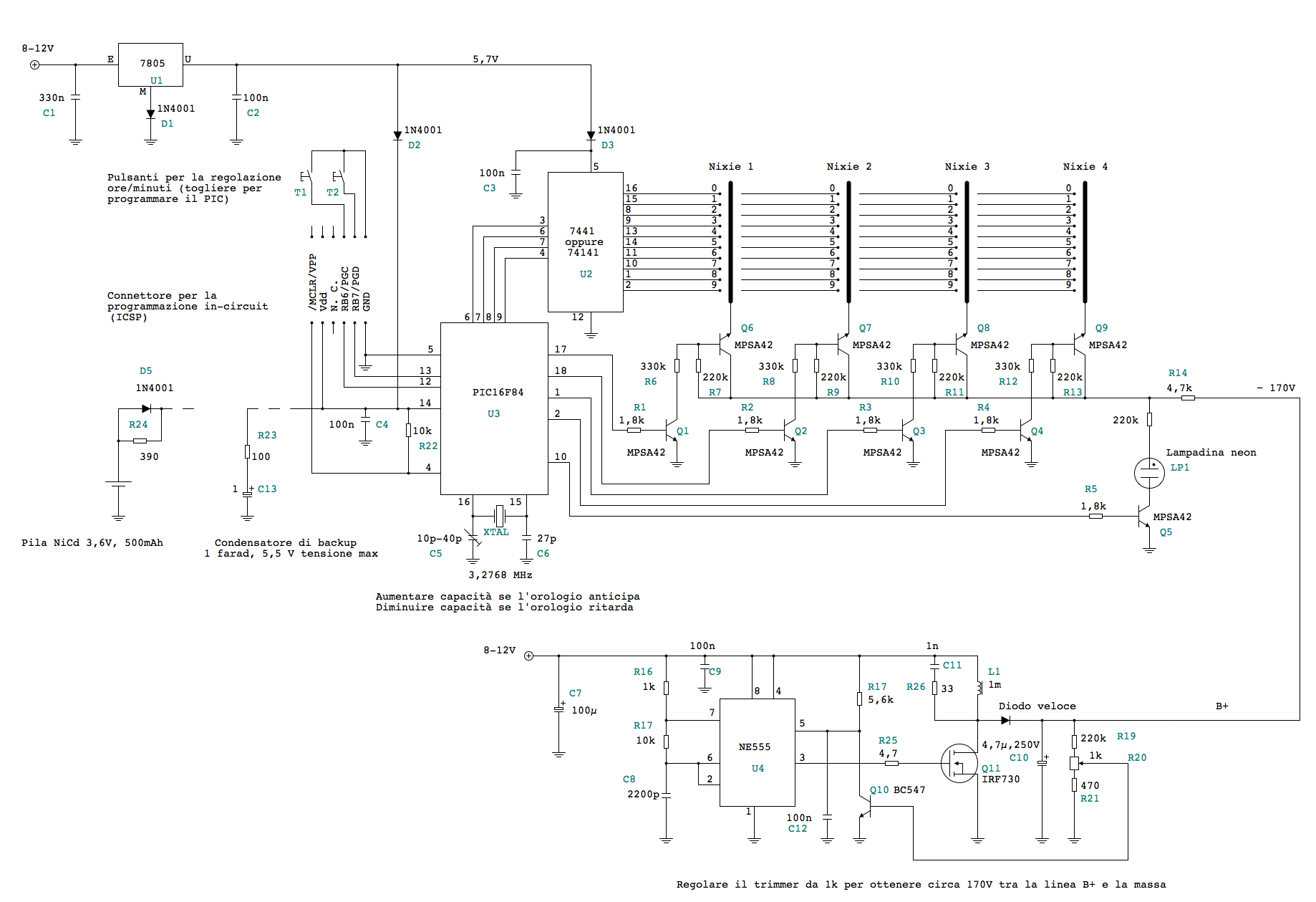
You can download and edit the circuit diagram contained in the file orologio_nixie_2_1.fcd, in the FidoCadJ file format. FidoCadJ is a software written by myself and available here on the site. Very briefly, I recall that the NE555 is used in a converter to increase the non-stabilized supply (8-12 V) to 170 V, as required for the tubes. These are multiplexed through by the PIC16F84 firmware using an 7441 driver and a few transistors. A rechargeable battery of 3.6 V, or alternatively a 1 F capacitor, can be used to power the microcontroller during power interruptions. I made a few changes to the DC/DC converter (which originally was very similar to the solution adopted in some schemes offered by the site http://www.nixieclocks.de). In particular, I added the snubber network formed by R26 and C11 and R25 the resistor to the drain of MOSFET Q11. I also lowered the value of the resistor R18 and the capacitor C12 added, to avoid instability in some loading conditions. For the inductor, I used a 1 mH, capable of supporting a current of at least 600 mA without saturation of the core. The choice of the inductor is very delicate, because it affects a lot the performance of the entire converter. Another critical component is the resistor R24, which is responsible to keep the battery in a light load when the clock is supplied. Must ensure that the load current does not damage the battery even after a long period of operation.
La piastra
Having seen the work of Aldo and Marco Simonazzi, I said it was the right time to try to build the circuit using the method of direct transfer of toner for the PCB. I have a color laser printer, a HP 2600n. So I modified the work of the Simonazzis by using my FidoCadJ, and here is the result.
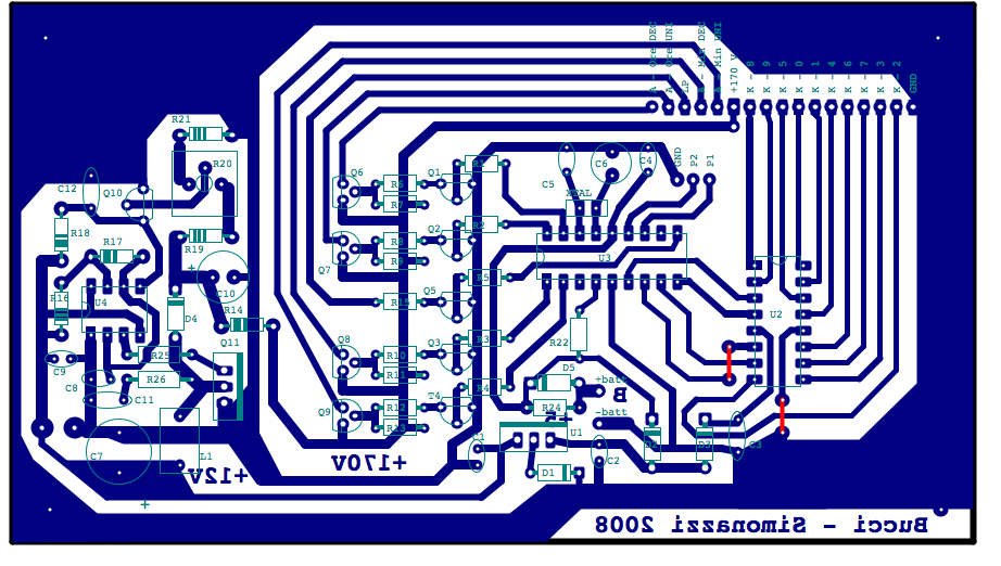
In the picture, the PCB is drawn component side with blue tracks indicating copper, blue/green screen for the silkscreen and the red indicating bridges. The all circuit is slightly smaller than an Eurocard (9 cm x 15 cm). The result is bigger than the first breadboarded prototype, where I could get a significative component density. I prefer avoiding issues, when building PCBs.
The file clockpic_unapiastra.fcd contains the circuit layout in the FidoCadJ format.
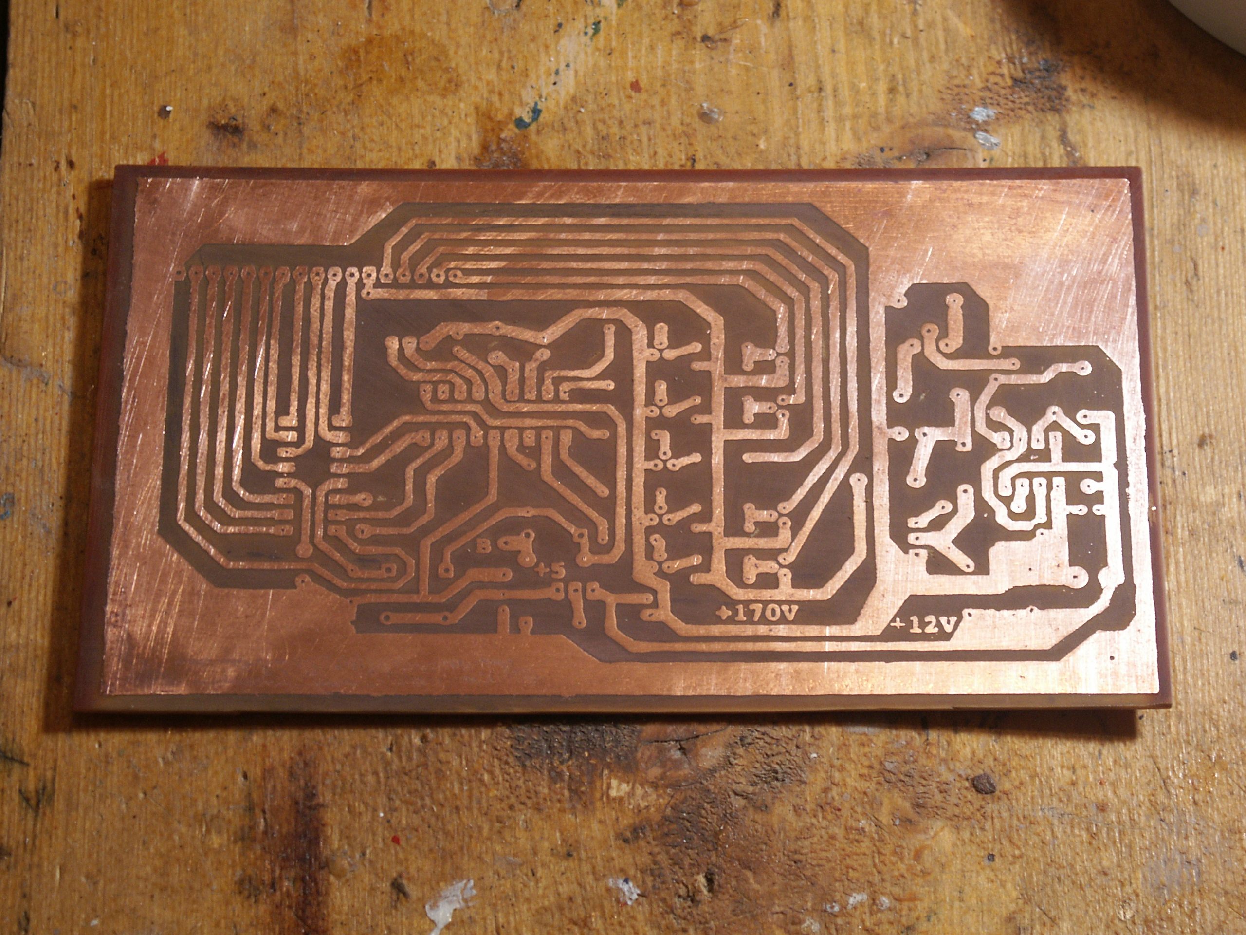
The direct transfer of the toner is a technique based on printing the circuit on a sheet of glossy paper and put it in contact with the copper side of the board. The toner is then thermally transfered with... ironing, and can be used for the chemical etching. You can easily find a lot of tutorials for this technique. In any case, it is difficult to find a glossy paper well adapted to this technique. Here is the result, with the toner adhering to the copper, before etching. Better results can be obtained.
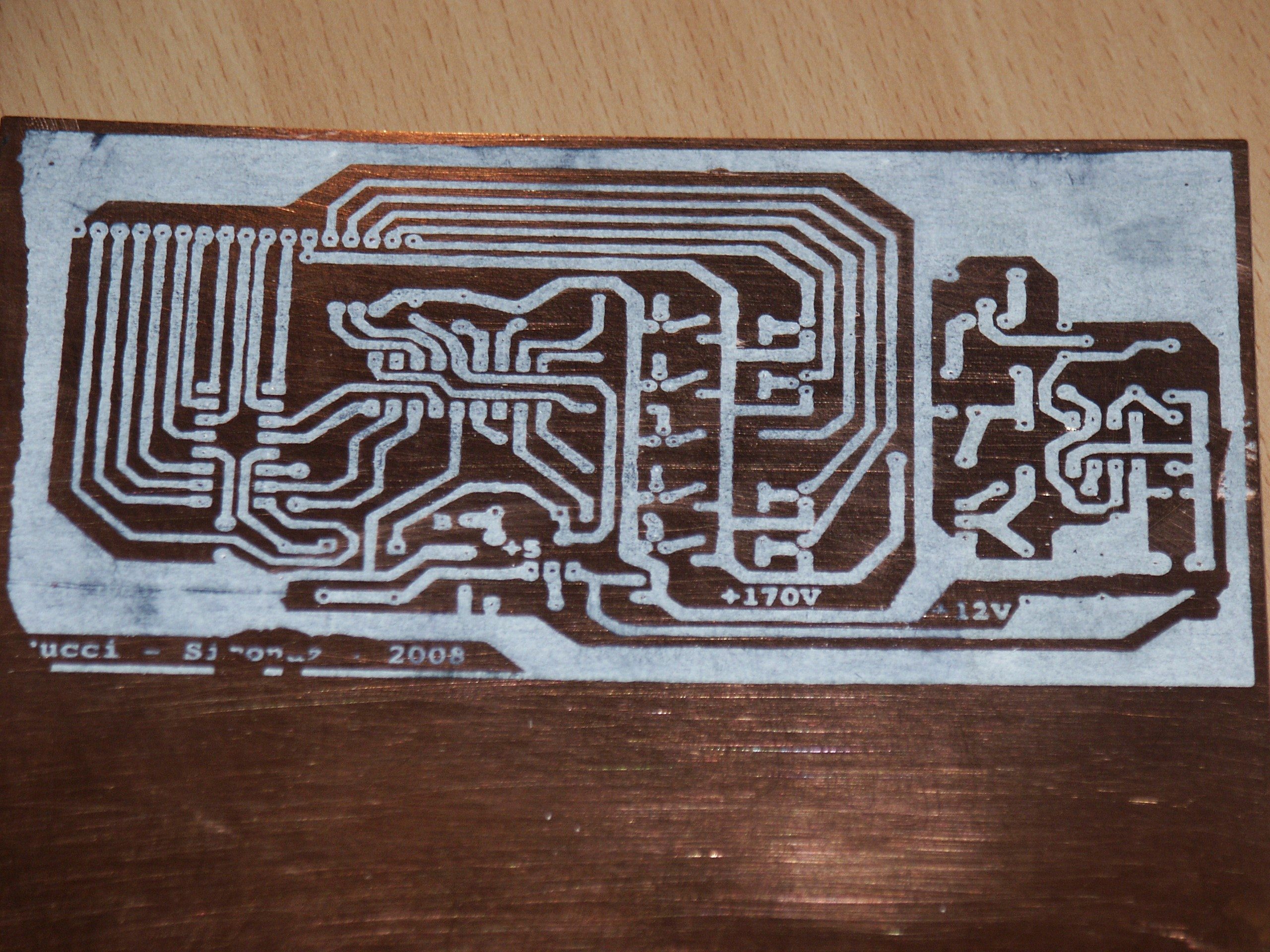
I thus retouched with a permanent felt the borders of the board, where the toner did not adhere to the copper, and then I etched everything.
Here is a picture of the etched board:
And here is the complete circuit, without the nixie tubes:
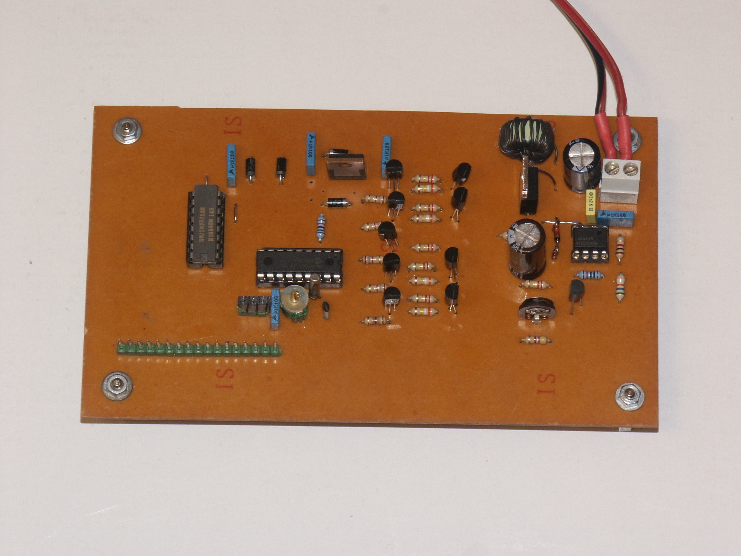
Several years ago, I savaged some Backelite substrates and this gives some sort of a "vintage" air to the circuit...
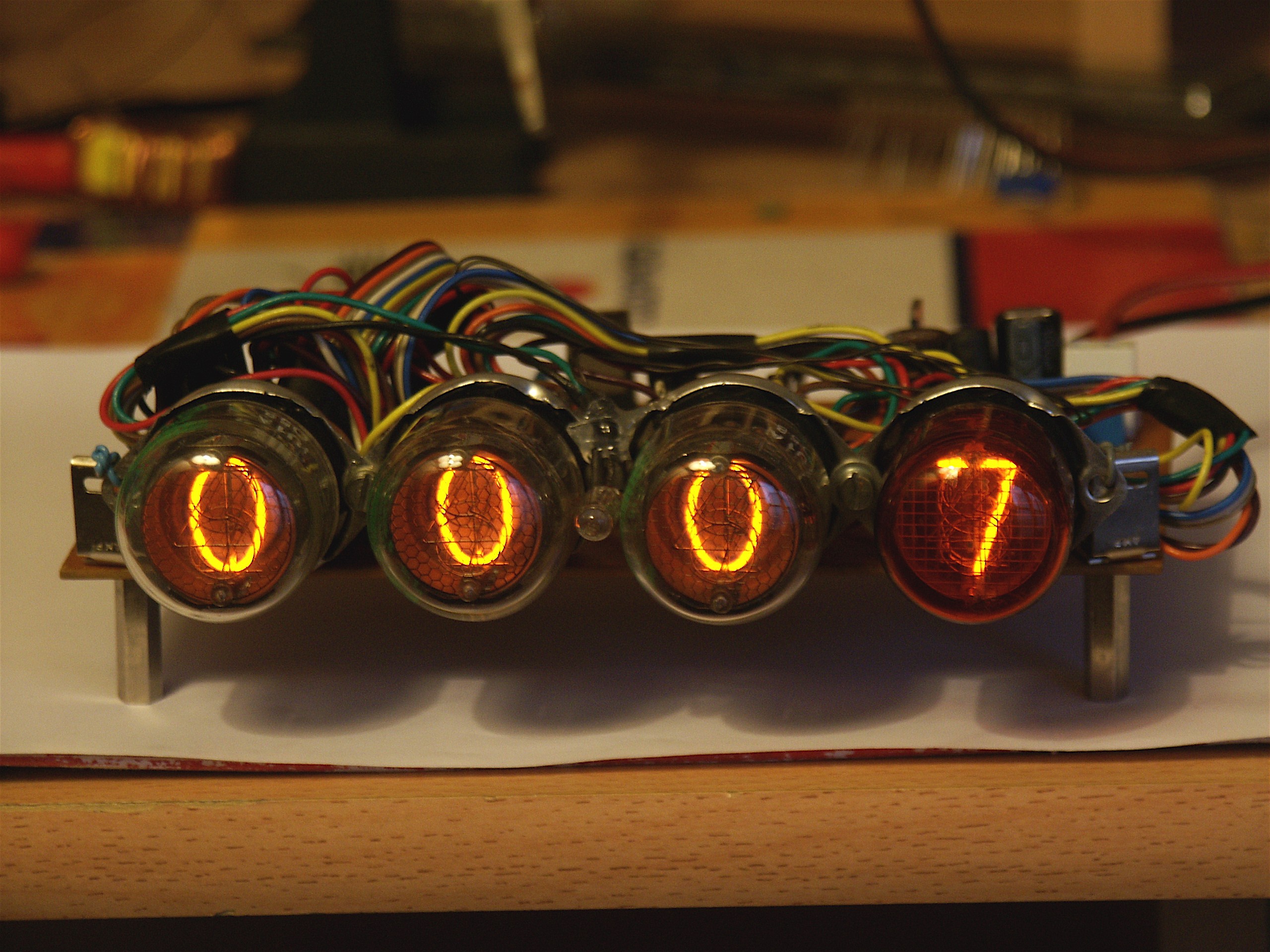
Here is the circuit while working with the four nixie tubes connected. The wiring order is indicated by the silkscreen.
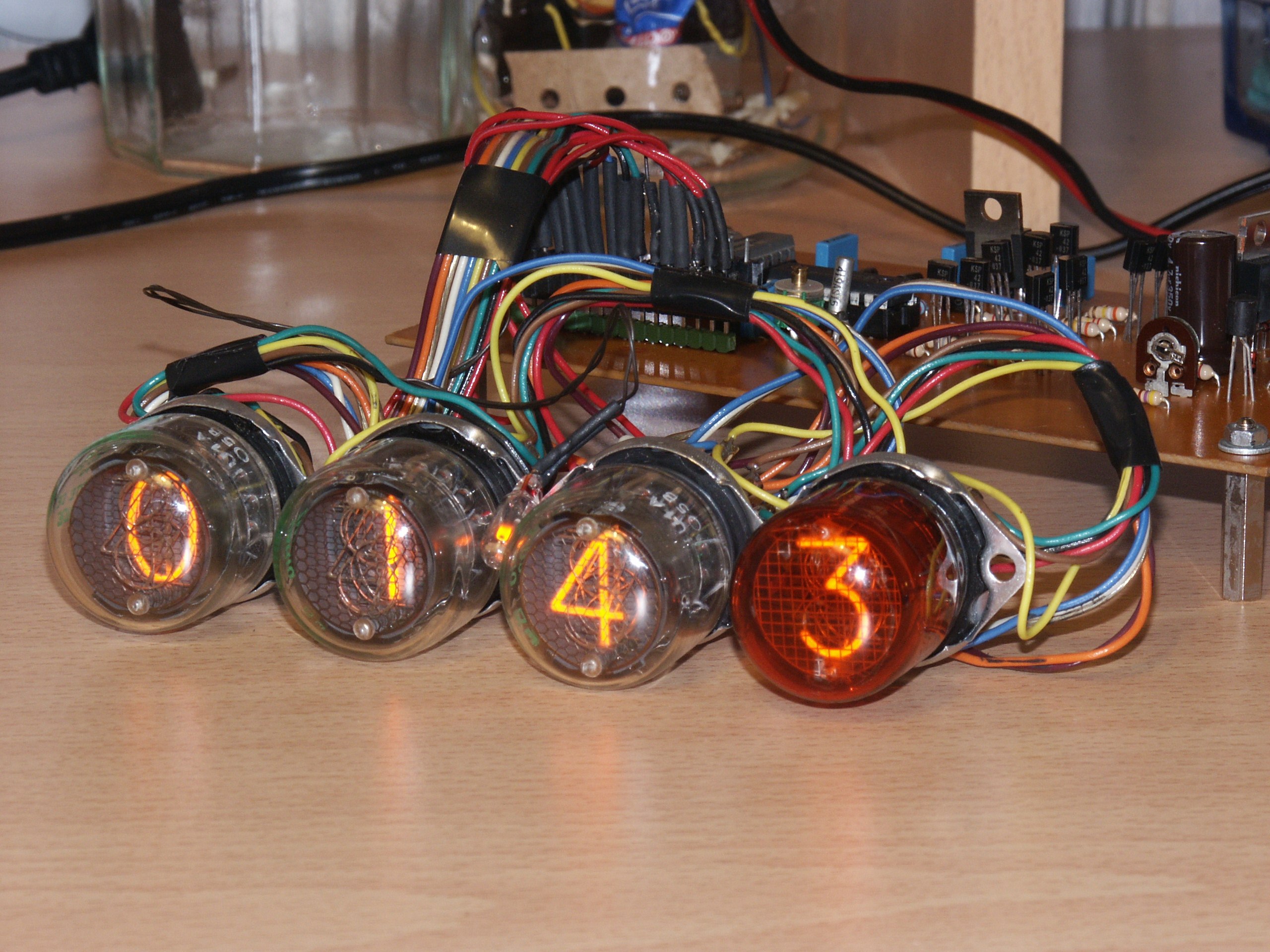
This second prototype needed something between 150 mA and 200 mA. It is therefore more efficient than the first one, shown here.
The firmware
Here is the source file, in the PIC assembly language: NixieClock.asm
Here is the compiled HEX file, which can be uploaded on the microcontroller: NixieClock.hex
Conclusion
We discussed here the realization of a nixie tube clock, and we have seen the circuit as well as the layout on a printed circuit board. In particular, the PCB make it relatively easy to build it, since much of the connections have already been done. Minimum experience and a skilled hand are nevertheless necessary for this project.
If you fabricate this circuit, I will be happy to receive some photos of what you built. A feedback of what you think of it will also be very welcomed.
 License:


--------

    Copyright (C) 2007-2008  Davide Bucci     davbucciPleasenospamherE@tiscali.it

    This program is free software; you can redistribute it and/or modify
    it under the terms of the GNU General Public License as published by
    the Free Software Foundation; either version 2 of the License, or
    (at your option) any later version.

    This program is distributed in the hope that it will be useful,
    but WITHOUT ANY WARRANTY; without even the implied warranty of
    MERCHANTABILITY or FITNESS FOR A PARTICULAR PURPOSE.  See the
    GNU General Public License for more details.

    You should have received a copy of the GNU General Public License
    along with this program; if not, write to the Free Software
    Foundation, Inc., 675 Mass Ave, Cambridge, MA 02139, USA.