
A wall clock with PIC16F84 and PCF8573, first part
Introduction
While tearing down an old VCR (a friend of mine gave it to me for that), I begun to search for datasheets of the various integrated circuits used in it. Among others, I found one which intrigued me and it was the PCF8573, a real time produced at the time by Philips (now NXP). It is a complete clock able to tell the time and the day via a I2C bus (see The serial protocol I2C with a 16F84 PIC). The most interesting thing was that the integrated this circuit needs very few external components to work. I thought it was a nice opportunity to build an original clock.
Before starting describing the project, I would like to point out a detail: I used a PCF8573 and a PIC 16F84. The latter has a quartz crystal oscillator for the clock, so it can accomplish alone the functions needed for a clock (interested readers might give it a try). PCF8573 can work using a NiCd single cell rechargeable battery providing 1.2 V for several weeks when the power supply is absent.

In this project, two points are for me particularly interesting:
- how to set up a serial communication on a I2C bus
- how to handle 8 multiplexed 7-segments LED displays.
For the first point, a detailed description is given in this page. The second point is interesting since the proposed solution involves only 6 I/O pins of the microcontroller to handle the displays.
In the second part of the project, I describe also how to connect 60 leds to represent the seconds.
Circuit description
The electrical circuit is quite simple: 4 integrated circuits, a handful of resistances and NPN transistors as well as the 8 displays. We begin our description with the most interesting devices, which are the PIC 16F84, the CD4511 and the CD4017. In the multiplexing technique, the retina persistance allows to optimize the number of I/O lines needed to control the displays. In fact, the simple principle is that only one display is on at each time, but they are activated in sequence at a frequency sufficient to make sort that it seems that all of them are on at the same time.
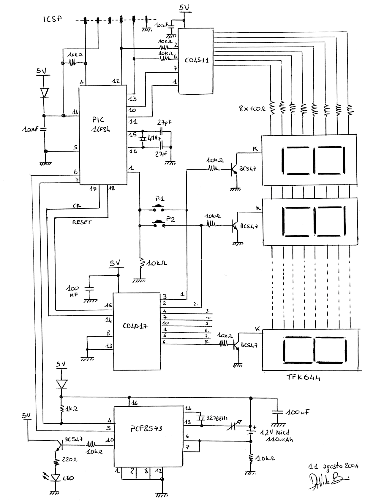
If the frequency is high enough (50 is OK), the technique works quite well. The CD4017 is a Johnson-type decimal counter. Each time a pulse is sent on the pin 14 (CK), it transfers a high logical level on its outputs, following the sequence: 3, 2, 4, 7, 10, 1, 5, 6, 9, 11. The sequence then restarts from pin number 3. In our circuit, this counter is used to activate displays one by one, thanks to the driver transistors which controls the display's cathodes. A pulse on pin 15 (RESET) to the CD4017 allows to start again the counting.
The CD4511 part is a display driver: it determines which segments to light up when a certain BCD code is given to its inputs (pins 2, 7, 6 and 1). In our case, it allows to ease the work of the microcontroller and to spare a few I/O lines.
To summarize what happens is that immediately after the RESET of CD4017, the first display is actif and shows the code specified on the control lines of the CD4511. The situation changes when a pulse is sent to the CD4017 clock input. In fact, the second display becomes the active one and the data is changed according to the number to be shown. The process is repeated quite fast for each display and then it is started again.
The display brightness is somewhat reduced by the fact that they are not continuously lit, we must choose a high brightness common-cathode display, such as TFK644, which is apt to multiplexing operation.
The outputs of the CD4017 that are used to activate the displays through the transistors can also be exploited to monitor the state of push buttons (P1 and P2 in the schematic), using only one microcontroller input. While multiplexing, there is only one display activated each time and the microcontroller monitors the state of only one button. With only six outputs and one input, it can handle 10 displays and can monitor the status of 10 buttons or switches. Not bad, and using only very common parts!
While the CD4017 and CD4511 deal with displays and buttons, PCF8573 integrated circuit constitutes the very heart of the circuit. It is a complete real-time clock, it can also compute the date and is fully controlled by I2C bus bus. The microcontroller periodically reads the date and time via the bus and displays them, allowing the user to adjust every parameter via a simple push button interface.
Components surrounding the PCF8573 are a 32768 Hz miniature quartz used to provide the time reference, a compensator to fine tune the timing if the clock is too fast or slow, a NiCd battery. BC547 is an NPN transistor used to flash two light emitting diodes each second, to be mounted eventually between the hours and minutes. The resistance of 10 kΩ always applies a trickle charge to the NiCd battery.
For the PIC programming, there is the ICSP connector (In Circuit Serial Programming). It allows to access all the lines useful to program the microcontroller in the circuit. This considerably eases writing and debugging the firmware.
The PIC16F84 firmware
The code executed by the microcontroller is divided into two very different parts. The first handles the communication with the PCF8573 through the I2C bus, and implements the functions described in this page.
The second is the interrupt handler and controls the display multiplexing. Inside the PIC16F84 there is a counter that can be synchronized with the master clock, so as to rise an interrupt at specific time intervals. When the microcontroller receives an interrupt, it temporarily stops the execution of the code and jumps to a function (the interrupt handler), which is responsible for updating the display cyclically. The normal execution then resumes from the point where the interruption occurred.
In the code, a memory location (called a file in the PIC jargon) is associated to each display. It is precious to represent the content to be handled by the multiplexing display routines. The PIC firmware basically updates the values there following what it is obtained by the PCF8573.
Download the assembler source code for the PIC
Power supply
The circuit requires DC 5 V with a maximum current of 75 mA. For that reason, a battery would not last very long. You may adopt a wall wart providing an unregulated voltage of at least 7V, followed by a 7805 voltage regulator which might be installed in the clock circuit.
 License:
 --------

    Copyright (C) 2004  Davide Bucci     davbucciPleasenospamherE@tiscali.it

    This program is free software; you can redistribute it and/or modify
    it under the terms of the GNU General Public License as published by
    the Free Software Foundation; either version 2 of the License, or
    (at your option) any later version.

    This program is distributed in the hope that it will be useful,
    but WITHOUT ANY WARRANTY; without even the implied warranty of
    MERCHANTABILITY or FITNESS FOR A PARTICULAR PURPOSE.  See the
    GNU General Public License for more details.

    You should have received a copy of the GNU General Public License
    along with this program; if not, write to the Free Software
    Foundation, Inc., 675 Mass Ave, Cambridge, MA 02139, USA.