
Bitbanging on I2C with a PIC micro
Note written in 2013: I wrote this article in 2004 and some things have changed since then. In fact, Philips does not fabricate semiconductor devices anymore since activity has be spun off in a new company called NXP. Then, the 16F84 PIC was already obsolete then, now is nothing more than a curiosity. However, some concepts are still useful today and the article might be worth reading.
Note written in 2016: Indeed, it seems that someone still reads this page! I thank Tom Lillevig for pointing out an error in the "i2cwaitack" routine.
Note written in October 2020: yes, this page is definitely still being read. Many thanks to István Sándor for having pointed out a minor discrepancy in the code.
What it can be done
All the hardware stuff
The software
The protocol
When things go wrong...
Conclusion
Correction suggested in January 2016
Introduction
In modern electronics, digital circuits tend to increase their complexity. New integrated circuits become available and can accomplish very complicated tasks. On another hand, the availability of cheap microcontrollers easy to be used by hobbyists (such as PIC's, the ST6 and 7, the Motorola 68HC11 and so on) allows to build interesting circuits.
One of the factors which determine the cost of a microcontroller or a programmable logic array (Altera, Lattice, Maxim, ...) is the number of input/output pins. In other words, with the same computing power and market strategy, a microcontroller sporting 24 input/output pins tends to cost more than one having only 13 of them.
The I2C bus is a system proposed by Philips in the mid 1980's. It allows to control a very wide family of integrated devices using only two I/O lines and the ground. It is therefore a very cost-effective solution of a serial communication working at different speeds (100 kbit/s, 400 kbit/s and more recently 3.4 Mbit/s). Several devices can be connected at the same time and each of them is addressed via a specific code.
In this document, we describe some bitbanging routines for the PIC16F84. They might be useful for other 8-bit PIC microcontrollers, where the hardware USART is not available.
What it can be done
Most of the devices using the I2C are fabricated by Philips, but a lot of other producers adopts the standard, which has become widespread. Among the devices offered by Philips, we find clocks and calendars (PCF8574, PCF8584), static RAM (PCF8570), EEPROM (PCF8582, 24C01), analog to digital converters (PCF8591) and the list is far from exhaustive.
With a PCF8574 integrated circuit, it is for example possible to add 8 input output bi-directional pins to a microcontroller. If you consider that it is possible to use 8 devices, you can add 64 I/O lines controlled by just 2 pins of the micro. If you own a model railway, for example, you can control all the railroad switches, or the lights with just 2 lines. With the PCF8575, the I/O pins become 16 for each chip...
On the Philips website, you can find a wide area dedicated to the I2C standard you can visit to have a more detailed idea of what you can do.
In this article, we describe how to control in a very simple way an I2C bus, using a 16F84 PIC microcontroller. The communication speed is the slowest one allowed by the standard (100 kbit/s) and we will deal only a simple situation where the microcontroller is the only device handling the communication clock. I do not want to describe in detail all the standard (you have a lot of interesting documents such as the I2C bus specification).
All the hardware stuff
The I2C bus is composed by two bi-directional lines and the ground return. The first line is called SCK and it is the synchronous communication clock. The second line, SDA is the line when the data are transferred between the devices. The protocol is therefore synchronous (serial communication via RS232 is instead asynchronous and more complex on certains points of view).
Since more than one controlled device may be present on the bus lines, the connections are made employing an open drain (wired or) strategy, as shown in Fig. 1. There is therefore a pull-up resistance for each line. Each device can thus connect the lines with the ground via a MOSFET (hence the name open drain), or be in a high impedance state allowing the pull-up resistor to impose a 1 logic level. In this way, there is no risk of current overload when conflicts appear on the bus.
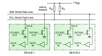
Fig. 1: the connection of several devices in a wired-or configuration (from the Philips I2C bus specification).
We will imagine being in the simple situation where there is just one transmitter and one receiver on the I2C bus. In reality, two kinds of devices exists: the master which is in charge of controlling the clock on the SCK line, and the slave which follows the clock imposed by the master. Note that the master device can be a receiver and the slave can transmit on SDA, or vice versa at a different moment of the transmission. As a general rule, however, on a I2C bus there can be only one master device and any number of slaves.
In our simple example, we have only a simple device connected to the microcontroller. Most often, the microcontroller will be the master device. In other words, the SCK line is always handled by the microcontroller, whereas the SDA line is bi-directional. We start by giving a few definitions in order to understand more easily the code we are going to write:
; ****************************************************************
; I2C routines developed by Davide Bucci, version 1.0, August 2004
; ****************************************************************

; Control lines of the I2C interface
SCL     equ     00
SDA     equ     01
I2CPORT equ     PORTB
I2CTRIS equ     TRISB

; Variables, substitute adresses of free RAM bytes
TMP     equ     0C      ; Dummy variable
COM     equ     10      ; I2C Communication Register
In our example, the SCL and SDA lines are to be connected with bits 0 and 1 of the B port of the PIC16F84, with a pull-up resistor tied to the positive power supply rail. The choice of the values can be done by keeping in mind that larger values decrease the supply current, where smaller values increase the speed and the noise margin but increase power consumption. In most cases, 10 kΩ is a good trade-off value.
The software
Things get more complicated with software, since we have to control the lines in order to communicate on the I2C bus via bitbanging. Each communication is a sequence of several bytes and each byte is sent starting from the most significative bits. Generally, the SDA line must be set up only when the SCK line is high, as visible in Fig. 2. There are two important exceptions to this rule. In fact, when the bus is not used, all two lines are kept high. The microcontroller starts the communication by putting a low state on SDA while SCK is kept high. Here is the code useful for starting a communication:
i2cstart                        ; Send a start on the I2C bus
        BANKSEL I2CTRIS
        bcf     I2CTRIS, SDA    ; SDA as output
        bcf     I2CTRIS, SCL    ; SCL as output
        BANKSEL I2CPORT

        bsf     I2CPORT, SDA      ; The start condition on the I2C bus
        bsf     I2CPORT, SCL      ; An high to low transition when SCL is high
        call    shortdelay
        bcf     I2CPORT, SDA
        call    shortdelay
        bcf     I2CPORT, SCL
        call    shortdelay      ; Leave SDA and SCL low
        return
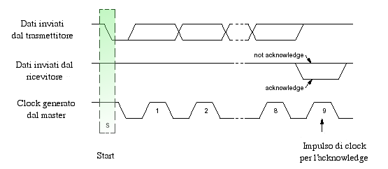
Fig. 2: the start condition, inspired from Philips datasheets.
In the code, we used the shortdelay function who introduces a delay in order to leave to the receiver enough time to react. With a 4 MHz crystal, a reasonable implementation (even a bit too long) of this delay routine is as follows:
shortdelay                      ; A short delay ;-)
        nop
        nop
        nop
        return
A symmetrical condition is the stop, which gives the end of transmission information. A transition of SDA from high to low when SCK is high.
i2cstop                          ; Send a stop on the I2C bus
        BANKSEL I2CTRIS
        bcf     I2CTRIS, SDA     ; SDA as output
        BANKSEL I2CPORT
        bcf    I2CPORT, SCL
        bcf     I2CPORT, SDA     ; The stop condition on the bus I2C
        call    shortdelay
        bsf     I2CPORT, SCL     ; A low to high transition when SCL is high
        call    shortdelay
        bsf     I2CPORT, SDA
        call    shortdelay       ; SCL and SDA lines are left high
        return
At this point things become more delicate and we have to deal with the communication. The bits are sent one by one from the most significative one. Each time the sender has completed a byte, the receiver gives an acknowledgment to say if everything was OK or there has been a problem. The microcontroller relinquishes the SDA line and the acknowledgment is done by the receiver by keeping SDA at a low state. The code of the send routine is as follows:
i2csend                         ; Send a byte over the I2C interface,
        movwf   COM             ; return 0x00 if ACK
        movlw   0x08
        movwf   TMP             ; TMP is used as a counter
        BANKSEL I2CTRIS
        bcf     I2CTRIS, SDA    ; SDA as output
        BANKSEL I2CPORT
icloops
        bcf     I2CPORT, SCL    ; Clock low: change of SDA allowed
        rlf     COM,f
        bcf     I2CPORT, SDA
        btfsc   STATUS, C       ; Test the carry bit
        bsf     I2CPORT, SDA
        call    shortdelay
        bsf     I2CPORT, SCL    ; Clock high
        call    shortdelay
        decfsz  TMP,f
        goto    icloops         ; i2cwaitack follows directly
i2cwaitack
        bsf     I2CPORT, SDA
        BANKSEL I2CTRIS
        bsf     I2CTRIS, SDA    ; SDA as input
        BANKSEL I2CPORT
        bcf     I2CPORT, SCL    ; Clock low
        call    shortdelay
        bsf     I2CPORT, SCL    ; Clock high
        call    shortdelay
        movlw   0x00            ; Ox00 in w means ack
        btfsc   I2CPORT, SDA    ; SDA low means ack
        movlw   0xFF            ; 0xFF in w means no ack
        BANKSEL I2CPORT         ; Clock is left low
        bcf     I2CPORT, SCL
        BANKSEL I2CTRIS
        bcf     I2CTRIS, SDA    ; SDA as output
        BANKSEL I2CPORT
        call    shortdelay
        return

; This version of i2cwaitack can be a little bit too fast for some i2c devices
; such as some EEPROM's.
; It may be convenient to introduce a timeout mechanism when waiting for the
; acknowledge.
; Refer to your device datasheet for more details.
Once the i2csend has completed, the w register will contain 0x00 if everything has gone OK, or 0xFF if the acknowledgment was missing and there has been an issue somewhere. The code to receive a bit is as follows:
i2creceive
        clrf    COM            ; Receive a byte over the I2C interface
        movlw   0x08
        movwf   TMP            ; TMP is used as a counter
        BANKSEL I2CTRIS
        bsf     I2CTRIS, SDA   ; SDA as input
        BANKSEL I2CPORT
icloopr
        bcf     I2CPORT, SCL   ; Clock low: change of SDA allowed
        call    shortdelay
        bsf     I2CPORT, SCL   ; Clock high
        call    shortdelay
        bcf     STATUS, C      ; Clear the carry
        rlf     COM,f
        btfsc   I2CPORT, SDA   ; Test the bit being received
        bsf     COM,0          ; Stock the bit read in COM and rotate
        decfsz  TMP,
        goto    icloopr
        movf    COM,w
        bcf     I2CPORT, SCL   ; Clock is left low
        call    shortdelay
        return
Once a byte has been received from I2C, program execution is returned to the caller and register w contains the received byte. Since the microcontroller is the receiver, it should give the acknowledgment to the sender if everything was received correctly. Calling the following routines acknowledges or not the transmission:
i2csendack
        BANKSEL I2CTRIS
        bcf     I2CTRIS, SDA   ; SDA as output
        BANKSEL I2CPORT
        bcf     I2CPORT, SCL   ; Clock low: change of SDA allowed
        call    shortdelay
        bcf     I2CPORT, SDA   ; SDA low means ack
        call    shortdelay
        bsf     I2CPORT, SCL   ; Clock high
        call    shortdelay
        bcf     I2CPORT, SCL   ; Clock is left low
        return


i2cnoack
        BANKSEL I2CTRIS
        bcf     I2CTRIS, SDA   ; SDA as output
        BANKSEL I2CPORT
        bcf     I2CPORT, SCL   ; Clock low: change of SDA allowed
        call    shortdelay
        bsf     I2CPORT, SDA   ; SDA high means no ack
        call    shortdelay
        bsf     I2CPORT, SCL   ; Clock high
        call    shortdelay
        bcf     I2CPORT, SCL
        return                 ; Clock is left low
The protocol
We described briefly the base operations involved in the communication: sending a byte, waiting for an acknowledgment, receiving a byte and sending (or not) an acknowledgment. Now, we have to see how those operations are used in the communication protocol in order to let two devices communicate. It should be noted that in this case several details depend upon the devices chosen. The best thing you can do is to refer to the datasheet of the different products to see the exact procedures. Some ideas are almost universal, however.
The first operation from the master is sending a start, followed by a byte which is always the 7-bit address of the device to be selected. Figure 3 shows an example of the address byte of a PCF8573, a real time clock.
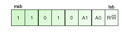
Fig. 3: the address byte compiled for a PCF8573 device (Philips datasheet).
The 7 bits are composed by two groups of bytes. The first part is usually 2 to 4 bits long and is determined from the logic state of several configuration pins on the device. You can therefore adopt more than one identical integrated circuit with different configuration states. The second part is always the same for each device of the same type.
For example, in the Philips PCF8573 chip, the fixed second part is always 1101, followed by a bit which is always zero. The first part can be configured depending on the state of pins A0 and A1 on the chip. We can therefore have 4 independent PCF8573's on the same bus.
The last bit of the first byte is the read/write bit. If the microcontroller wants to write something on the bus, it should be high, otherwise if it is expecting something from the slave device it should be low (as a master receiver, it should continue handling SCL).
The start condition may be repeated in a single transmission several times, in most cases when logically different chunks of the transmission should be split. An example is passing from reading to writing on the device etc. In this case (the code is identical), the i2cstart routine might be called more than once.
When things go wrong...
Even after a careful reading of datasheets, it happens rarely that circuits work at the first time. In fact, you can observe the state of I2C bus lines with special testers which show on a screen what happens there. A simpler solution may be to use an oscilloscope to see what happens on SCK and SDA. You can use the microcontroller to trigger the oscilloscope via a third I/O pin, continuously repeating the message if you do not have a digital oscilloscope with memory.
If you do not own an oscilloscope, you can use two LED's with two transistors in order to see what happens. The I2C protocol is static, so you can slow down considerably the transmission speed by modifying the shortdelay routine. You can follow bit by bit what happens on the lines simply with your eyes.
Conclusion
In this article, I wanted to introduce briefly the widespread I2C communication standard. Probably your VCR and your TV have dozens of chips using this standard. I also presented some PIC assembly code for bitbanging communication on I2C. My routines are not universal and they are published as they are without any warranty, under GPL v. 2. I would be happy to have a feedback if you used them.
Correction suggested in January 2016:
Tom Lillevig has kindly sent a note at the end of 2015 about my code. That shows that there is still an interest in those routines! Here is his remark:
Thank you for posting the information about I2C on your website and especially for the PIC assembly language software. I used your examples to help with my first I2C project. All of my PIC hobby projects are in assembly language. I did notice in the "i2cwaitack" routine that you change the SDA line back to an output before you set SCL low. I think that is an error because I believe that the slave will not release the SDA line until SCL goes low. The code works as you have written it but the PIC will be trying to drive SDA high for a few microseconds while the slave is still driving SDA low. I have changed the order of those instructions in my version. Thank you again for your efforts.
Tom Lillevig
I corrected the code above for the "i2cwaitack" routine including Tom's correction. The original code was as follows:
i2cwaitack
        bcf     I2CPORT, SCL    ; Clock low
        bsf     I2CPORT, SDA
        BANKSEL I2CTRIS
        bsf     I2CTRIS, SDA    ; SDA as input
        BANKSEL I2CPORT
        call    shortdelay
        bsf     I2CPORT, SCL    ; Clock high
        call    shortdelay
        movlw   0x00            ; Ox00 in w means ack
        btfsc   I2CPORT, SDA    ; SDA low means ack
        movlw   0xFF            ; 0xFF in w means no ack
        BANKSEL I2CTRIS
        bcf     I2CTRIS, SDA    ; SDA as output
        BANKSEL I2CPORT         ; Clock is left low
        bcf     I2CPORT, SCL
        call    shortdelay
        return
Log:
October 30, 2020 - Corrected a minor discrepancy (reference to PORTB instead of I2CPORT in i2cstart).
January 17, 2016 - Corrected the end of i2cwaitack and some typos in the Italian version of the page.
January 10, 2016 - Added Tom Lillevig's correction in the code.
May 26, 2013 - Review and English translation.
August 2004 - First version of the page.
License
 License:
 --------

    Copyright (C) 2004-2020  Davide Bucci davbucci at tiscali dot it

    This program is free software; you can redistribute it and/or modify
    it under the terms of the GNU General Public License as published by
    the Free Software Foundation; either version 2 of the License, or
    (at your option) any later version.

    This program is distributed in the hope that it will be useful,
    but WITHOUT ANY WARRANTY; without even the implied warranty of
    MERCHANTABILITY or FITNESS FOR A PARTICULAR PURPOSE.  See the
    GNU General Public License for more details.

    You should have received a copy of the GNU General Public License
    along with this program; if not, write to the Free Software
    Foundation, Inc., 675 Mass Ave, Cambridge, MA 02139, USA.