Playing with chaos
My implementation of the Chua's circuit
A first attempt, with a real inductor
A more configurable version with a GIC
My final circuit in action
Conclusion
Bibliography
Video.1: The output of my final circuit, in the "fast" mode, plot on the screen of an analog oscilloscope in the XY mode. More videos below!
Introduction
In autumn 1987, I went with my parents to Turin to visit an art exposition dedicated to Jean Tinguely. That day, sitting in the car behind them, I probably was a bored 8-years old kid, unaware of what a "contemporary art exposition" was. When my parents got the tickets and we stepped in the exposition's big hall, however, I was immediately hooked by Tinguely's dadaist world, made of funny-looking machines. I loved those complicated mechanisms, moving with no apparent practical purposes. Among the other things, I vividly remember a drawing machine where kids could put a sheet of paper and let the machine draw for them. I wish I conserved mine! I was so impressed and amused that I called Tinguely the goldfish which, shortly after, was my pet for a while. The memory of this experience was to resurface in my head almost thirty years later, in a rather unexpected way, in a quiet autumn evening spent playing with chaotic analog circuits.
The Chua's circuit was the first electronic circuit (discovered in 1983 [1]), where a chaotic behavior was visible. It is a simple oscillator which generates non-periodic signals. Two voltages are easily accessible and are usually plotted on an oscilloscope in XY mode, yielding a characteristic chaotic attractor known as the "double scroll".
In this article, I describe the Chua's circuits I built. By the way, I found lots of examples on oscilloscopes, yet it seems that using analog XY plotters is much less common. Watching them is somewhat hypnotic and reminds me those Tinguely's drawing machines I was so much delighted with when I was thirty years younger.
This article is organized as follows. At first, I will describe the standard version of the circuit, which employs an inductor. Then I will show a version where it is replaced by a general impedance converter (GIC) circuit. At the end, I show some of the videos I recorded with the circuit in action.
A first attempt, with a real inductor
The first circuit I tried is pretty straightforward and it is shown in figure 1 (by the way, if you like it, it is drawn with FidoCadJ). The most critical component of the circuit is the inductor. However, among my spare components, I have a certain number of them and I picked up one reasonably close to those employed in working circuits (such as in [2], but the Internet is literally full of Chua's circuits, so GIYF).
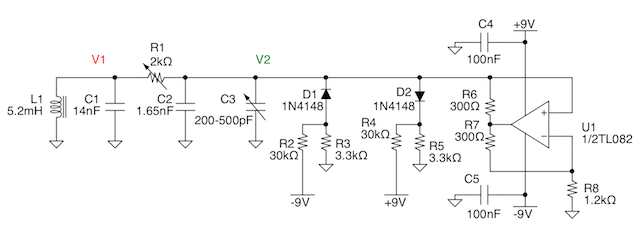
Fig.1: The first Chua's circuit, with a real inductor (click to enlarge). FidoCadJ's source here.
Chua's circuit is so famous that it has a Wikipedia entry for it [3], reporting the equations resulting from circuit analysis:

where x(t) and y(t) are respectively the voltages across capacitors C2 and C1 and z(t) is the current in the inductor L1. Parameters α and β depends on the choices done in the rest of the circuit and the nonlinearity is expressed in the nonlinear characteristic of f(x).
In fact, the inductor should have a relatively large value without having an excessive series parasitic resistance. R1 controls the tuning of the circuit and, to provide an additional degree of freedom, I put C3, an old variable capacitor in parallel with the C2 capacitor. This is not mandatory, but it allows to somewhat change the pictures drawn on the screen. D1, D2 and R2-R5 provide the nonlinearity of the circuit, as required to have a chaotic behavior. The first results were not mind-blowing, but showed that a chaotic behavior was indeed possible, as depicted in figure 2.
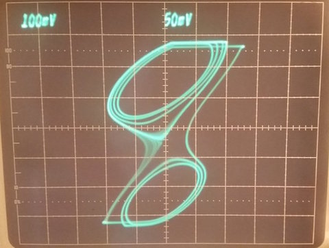
Fig.2: The first output I obtained playing with circuit shown in fig. 1 and an oscilloscope in XY mode. Not very spectacular, but hey, it's chaotic!
At that moment, I could try to improve the circuit I had, but since my goal was to try to use a XY analog plotter I had, I decided instead to change the strategy. In fact, increasing the time constants of the circuit would mean to increase the value of the inductor to utterly unpractical values. Therefore, I adopted a General Impedance Converter (GIC) to simulate it, instead of using a real one. This is not a new idea, of course, and it turns out that this is a good choice, as we will see in the following paragraphs.
A more configurable version with a GIC
Antoniou's GIC is a classical way an inductor can be simulated by means of a simple circuit employing two operational amplifiers [4]. Since the final value of the inductance will depend from the value of other components, it is easy to tune it by means of a simple potentiometer. This add a very useful degree of freedom which can be exploited in the circuit. My implementation is shown in figure 3.
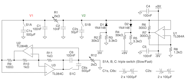
Fig.3: The second Chua's circuit, with the inductor simulated by a GIC (click to enlarge). FidoCadJ's source here.
The value of the inductor is given by the following equation:
 The triple switch S1 is used to increase more than of three orders of magnitude the capacitances which are employed in the circuit. In this way, the time constants are increased of the same amount and the evolution of the circuit is correspondingly slower. By employing the previous equation, for R12 at 1 kΩ we obtain a simulated inductance of 10 mH when the switch is open which increases up to 50 H when S1 is closed! This allow to obtain what I needed, i.e. to plot the results with an XY plotter.
My final circuit in action
After a successful test on the breadboard, I put the circuit of fig. 3 in a small plastic box that I bought a few years ago. I put the R1 and R12 potentiometers on the front panel along with the S1 switch and the two output BNC's for the X and Y signals (V1 and V2 in the schematic of fig. 3). Figure 4 shows the result.
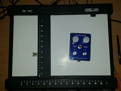
Fig.4: The circuit in the box, ready for action!
The front panel markings are laser printed on an ordinary sheet of paper, cut to the right size, plastified and then glued on the plastic box, as shown in figure 5. Such a simple technique yields satisfactory results for simple home projects like this one.
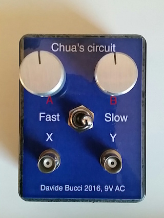
Fig.5: I printed the front panel with my laser printer, I plastified it ad I glued it on the top of the box. Simple and reasonably effective technique for small projects such as this one.
Something which is not detailed is the dual +/- 9V power supply circuit which operates from a single 9V AC input. The AC mains transformer is external to the box. In my, case, I had several LM723's laying around and I used two of them to regulate the positive and negative rails, with circuits taken directly from the LM723 datasheet; nothing very fancy but it works fairly well. Figure 6 shows the finished circuit, assembled on an universal board. It would be probably better to use only a positive 18 V rail and obtain a 9 V reference by means of a divider buffered by the spare operational amplifier of the TL084.
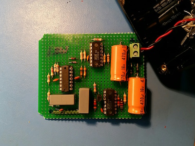
Fig.6: The circuit, on an universal board. It is the circuit shown in Fig.3, with a dual power supply obtained with two LM723's.
The capacitors C1s, C2s and C6s are unpolarized electrolytical capacitors which are obtained by putting in anti-series two identical capacitors having a capacitance which is the double of the one which has to be obtained. They are mounted directly behind the front panel, as shown in figure 7. All connections are made with a simple connector so that the circuit remains accessible.
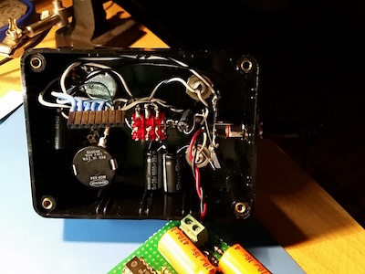
Fig.7: The backside of the front panel. The big black capacitors are for the "slow" mode and R1 is a 10-turn potentiometer.
Video 2 shows what I wanted to obtain: the Chua's double scroll attractor drawn by means of an old analog XY plotter. I think Tinguely would have loved that, even if it lacks the dadaistic power of his overly complicated Rube-Goldberg like machines. But, after all, I am no artist! I have a small collection of plastified Chua's attractors now!
Video.2: Here is the video of my circuit being connected to a vintage XY plotter. I personally found that watching a plotter while it draws an attractor is quite mesmerizing...
I have always loved the analog phosphor memory of vintage Tektronix oscilloscopes and I have obviously tried to plot an attractor with one of them, as shown in video 3. The results are also quite pleasing, at least for my tastes.
Video.3: The output of the circuit (in a slightly speeded up version) as recorded by a Tektronix analog phosphor memory oscilloscope.
Conclusion
In this article, I described how I played with my implementations of Chua's circuit. I first started from a simple circuit with a real inductor, then I employed a GIC to emulate it. In this second version, I could benefit from a greater circuit tuning range and I could slow down it considerably, so that I could employ a XY plotter to draw attractors.
I had a great fun playing with this circuit. I showed it to two kids which are a couple of friend's children and they loved it: the plotter produced two strange attractors for them and everybody was happy. Watching the videos of the plotter is certainly mesmerizing and I really enjoyed the time spent.
Bibliography
[1] - L.O. Chua "The genesis of Chua's Circuit" AEU, vol.46, n°4, 1992 (available online here)[2] - http://www.chuacircuits.com
[3] - Wikipedia's entry about Chua's circuit
[4] - S. Franco, "Design with Operational Amplifiers and Integrated Circuits" fourth edition, McGraw-Hill Education, New York, 2015
This article is also treated in a discussion (in italian language) on the ElectroYou forum. I would like to thank those who have found errors in this page!
Log:
November 11, 2016 - First version of the page, in English
November 12, 2016 - Correction of several typos (antiparallel -> antiseries, 100mH->10mH, error in fig. 3) and added more information on the inductance calculation.
November 14, 2016 - Typo correction, Italian translation from elfo. Corrected another stupid error in the schematic of fig. 3 (thanks IsidoroKZ!!!). Added a hint about power supply by GuidoB.
License

This work is licensed under a CC BY, NC 4.0 licence.
