



MIDI splitter with a PIC16F876
NOTE 14 August 2026: I wrote this short page in 2005, then revised it in 2007, 2013 and 2026. It is interesting to work again on a project that is more than twenty years old (I started it in 2004). It goes without saying that certain choices that seemed valid back then are no longer so today. One tends to use VST in a DAW for music production, but PICs still exist, as do MIDI devices. If you are interested in this project, please read the appendix I added in 2026 and make sure you are using firmware version 2.1 or later.The circuit
The firmware
My first prototype
Circuits built by other people
A possible improvement
Conclusion and acknowledgements
2026 addendum and the firmware v. 2.1
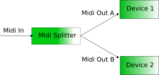
Fig. 1: The functional schematic of the MIDI splitter.
Introduction
The MIDI protocol is a widely used standard since a while in the musical field. Its goal is to let electronic instruments easily communicate. Examples include master keyboards, expanders, synthesizer, effect processors and much more.
Developed at the beginning of the 1980's, MIDI has gained a widespread diffusion thanks to its intrinsic advantages and low-cost. Simple and more complex MIDI interfaces can now be found on almost all electronic instruments which are a little more than toys. MIDI is an asynchronous serial communication protocol, working at a speed of 31.25 kbit/s, which is quite slow compared to urrent standards such as FireWire or USB.
From the user standpoint, a MIDI interface looks like two female 5-pins DIN connectors, called IN and OUT, often paired with a third one called THRU. The input port (IN) is a receiver for the messages saying which notes have to be played, and with which instruments. The output (OUT) obviously is symmetrical and is meant to receive the signal. To connect a keyboard equipped with a MIDI interface with a sound expander, one needs to connect the OUT port of the keyboard to the IN port of the expander.
From the communication protocol point of view, commands are sent via packets (messages) formed by a header, a body and a terminator. For each physical connection, 16 channels are available for messages. For example, a musician can use a piano associated to channel 0, a violin on channel 1, a viola on channel 2, a cello on channel 3 and so on. This way, each note played sent via the MIDI interface will be played by the right instrument, depending on which channel it is affected.
This article describes a project using a PIC16F876, meant to split MIDI message on two different outputs depending on the channel. This circuit therefore has one MIDI input and two outputs. For each received message, it recognizes the channel and routes it following a table held in memory of the microcontroller. Figure 1 shows a simple schematic view of this concept.
Such a project is useful for those like me, owning several MIDI instruments but a simple computer interface with only one physical output. This circuit in fact can be used to independently control two devices.
The circuit
I have chosen a flexible 4 MHz operated PIC, the resulting circuit is visible in figure 2 and is quite simple, since all the dirty work is done by the firmware. Watching the schematic, we see that the MIDI IN input is directly connected to an optocoupler. This device plays a protection role against potentially dangerous voltages, but much more frequently avoids that ground loops appear between the different instruments.
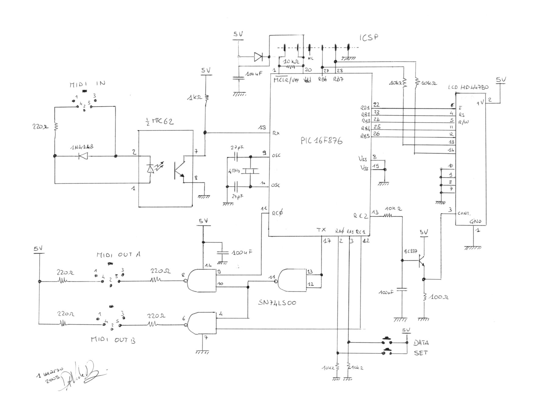
Fig. 2: The electrical schematic of the circuit. 2026 note: In the end, I found it simpler and more practical to use a simple potentiometer between 5V and GND, with the slider connected to pin 3 of the LCD display, instead of the transistor, the two resistors, and the capacitor.
I had a number of old MTC62 couplers obtained by a dismantled old clean room equipment (a RIE), and so I used one of them (just one half). Probably, by adjusting the pinout, it would be even better to use a fast optocoupler such as the PC900 by Sharp. In fact, this latter model is very often used for MIDI.
The input signal is then fed to pin 18 of the PIC, which is configured by the software to act as a serial receiver. The receive speed is configured by the firmware to follow the MIDI protocol. It is quite simple to receive serial data, since PIC16F876 sports a hardware USART that basically does everything you need for the communication. Apart the different hardware implementation, from the firmware standpoint using MIDI is not very different than using a RS-232. In fact, I saw several years ago some cheap MIDI interfaces meant to be plugged on the RS-232 ports.
The ICSP (In Circuit Serial Programming) connector gives access to all signals needed to program the microcontroller without having to remove it from the circuit. This is very useful while developing the firmware, if you have a programmer wich can use this fature. The B port of the PIC is devoted to the control of a HD44780 or compatible LCD display, showing 2 lines of 16 characters each. The display is precious for the user interface in order to show and change the routing table. To do that, two buttons called DATA and SET are connected to lines A0 and A1 are used for the interaction.
The MIDI message are sent again to pin 17, and then routed to the A or B MIDI outputs, thanks to the NAND gates in a SN74LS00. Those gates are controlled by the C0 and C1 outputs of the microcontroller.
A note of folklore: as I said above, I used an optocoupler from a dismantled clean room RIE equipment, and the SN74LS00 comes from a prehistoric scanning electron microscope. In reality, it would be better to choose a 74HC00 which guarantees a more generous output current handling, useful to power up a led.
The firmware
Here is the source code of the firmware, ready to be compiled with MPASM (or GPASM) and to be programmed on the PIC. The license is GPL. I tried to put some meaningful comments in the software, hoping that it will be easy to be adapted to your needs.
Source: MIDI_splitter.asmCompiled: MIDI_splitter.hex
The only thing the software must do is to receive the MIDI packets, recognize the channel of each message and route it towards the output specified in the routing table. Of course, this table must be modifiable by the user at any time and it must be stored in EEPROM, such as that it remains in memory during power off.
The PIC firmware is quite simple since all the difficult stuff concerning the serial communication is done by the hardware USART. In reality, we just have to configure it to the correct speed (31.25 kbit/s), 8 bits data with a stop bit and a start bit. The transmission is asynchronous, as specified by the MIDI standard. The USART rises an interruption automatically when a character has been correctly received and is stored in the communication buffer.
This way, everything that is related with the transmission and handling of MIDI signals takes place inside the interrupt, while the main loop is devoted to the (very simple) user interface. A MIDI message is composed by several bytes. The first one is the header and it is the only byte having the most significative bit set. The seven remaining bits are used to recognize the message type (3 bits) as well as the channel (on 4 bits).
Two types of messages exist: the first one is composed by messages effectively referred to a certain channel, the second one is composed by messages affecting the global configuration of the MIDI device thus not being specific to one particular channel.
In the interrupt handler, the presence of a message header is recognized via a test done on the most significative bit. If a header is found, the program extracts the channel number, as specified by the header and reads in the routing table where the channel has been routed. The physical routing is done by activating the C0 and C1 lines.
In the current version of the firmware, I have choosen not to give a complete handling of MIDI messages such as SDS o system exclusive, not associated to a particular channel. I should find the time to expand the code to handle this.
The microcontroller is in principle able to handle with PWM technique the LCD contrast, but for the moment this feature is not activated in the software since in my LCD the best contrast configuration is the one with the contrast pin tied to 0 V (see the 2026 note: put a potentiometer instead!).
The user interaction is done via two buttons. The DATA button moves the cursor through the menu elements, where the SET button changes the selected element. In the software, everything is handled via a state machine where each state corresponds to the active menu element and the action of the buttons (after debouncing) controls the state change.
My first prototype
I assembled my first prototype on a breadboard and I used a backlit display. The power supply is assured by a wall wart which gives more or less 8 V DC, from which the 5 V are obtained thanks to a uA7805 regulator. The required current is less than 100 mA.
I put everything in a metal box, drilling the front panel to show the display and the buttons needed for the user interface. I use classic decals to write on the aluminium panel, covered by thin layers of transparent coating.
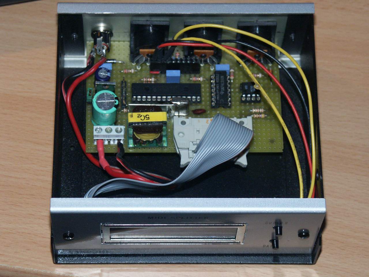
Fig. 3: The circuit in a box, open, seen from the front.
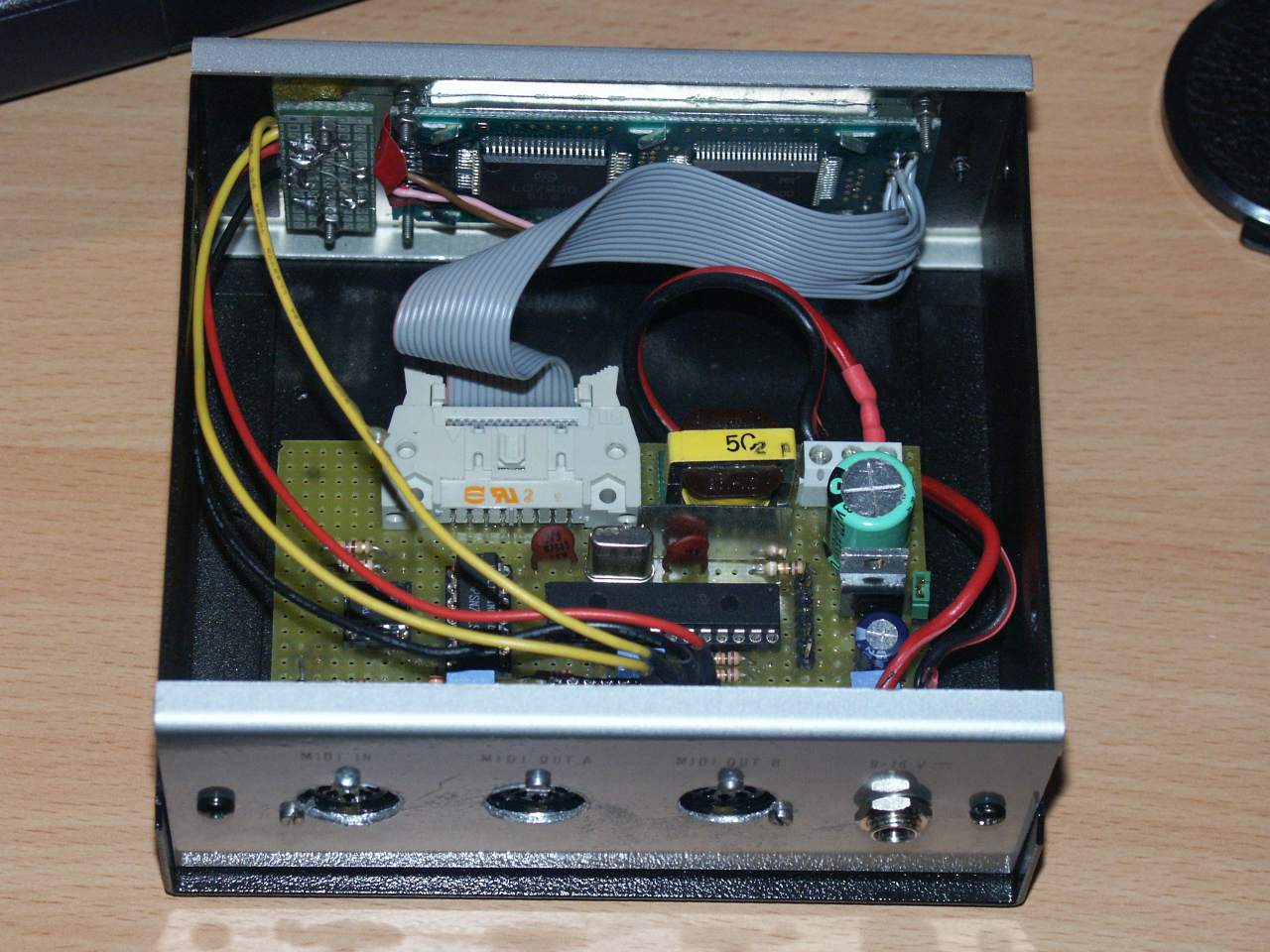
Fig. 4: The circuit in a box, open, seen from the back.
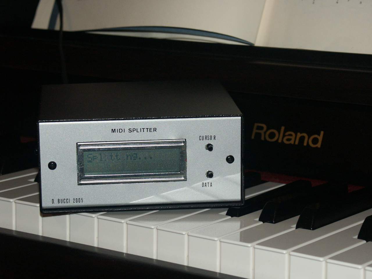
Fig. 5: The circuit in its box, seen from the front.
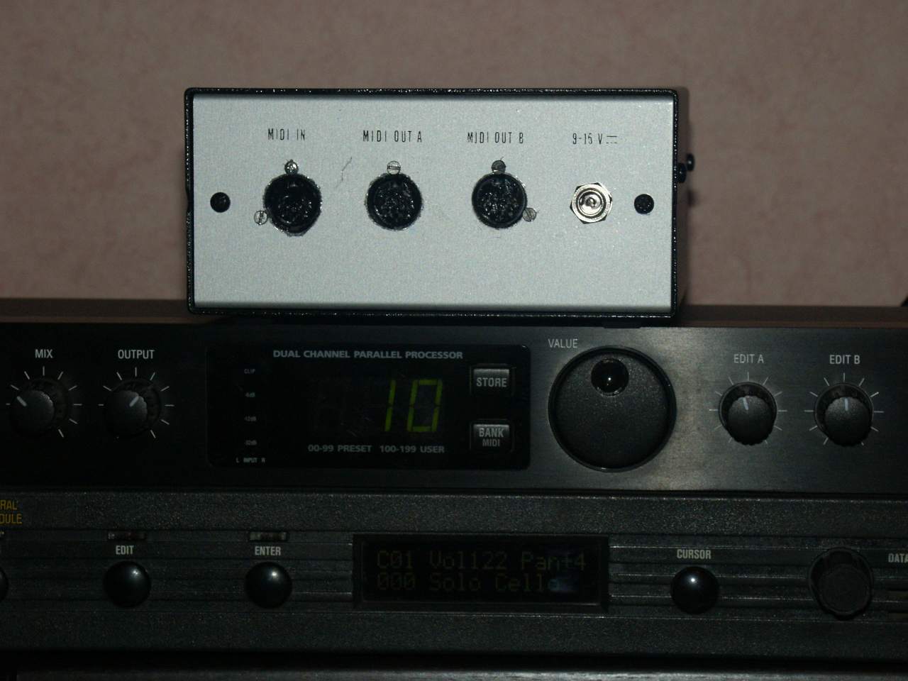
Fig. 6: The circuit in its box, seen from the back.
Circuits built by other people
Floriano
Since the publication of this page, I have seen with pleasure that this circuit rose some interest. In particular, in 2007 I have been contacted by Floriano, who has even fabricated a PCB and drawn in a much more elegant way my hand drawn schematic. Floriano used a CNY 17 photo coupler and has been obliged to rise to 27 kΩ the resistance between pin 18 of the PIC and the positive power supply rail in order the transmission is working flawlessly. He also added a LED to the original circuit to show the income of MIDI messages to the circuit.
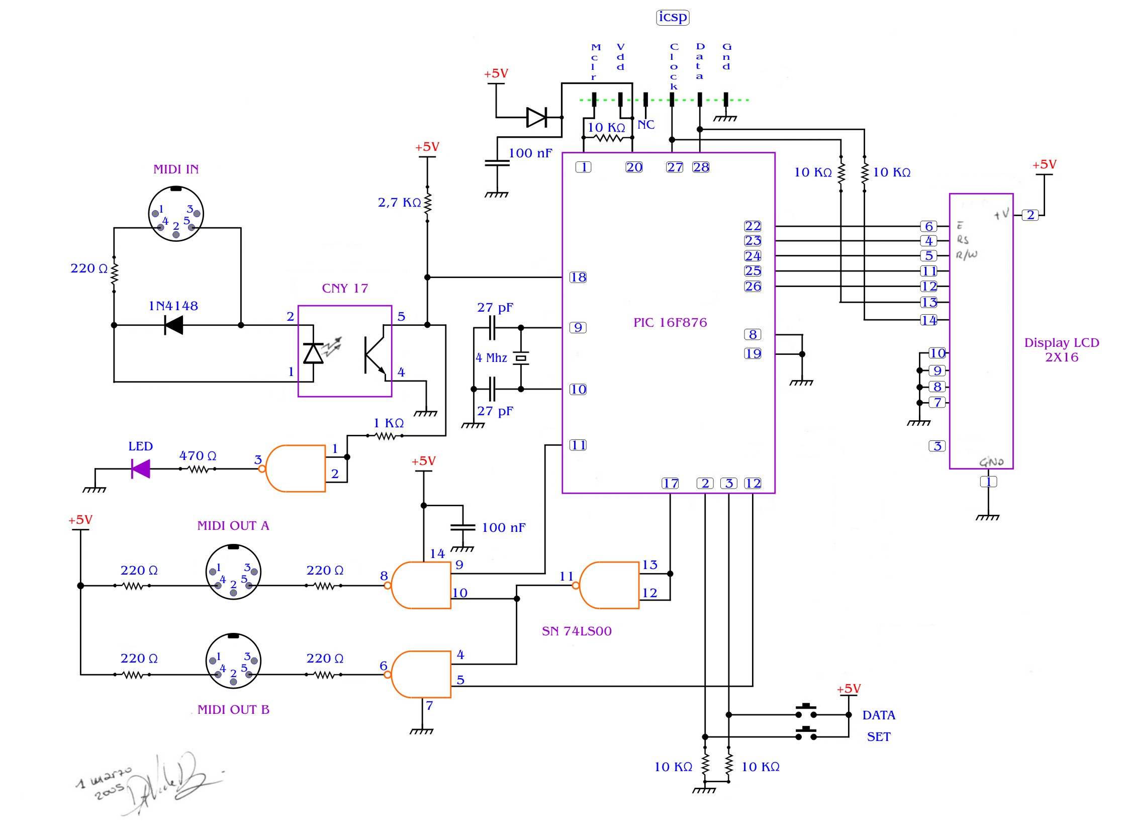
Fig. 7: The schematic, redrawn by Floriano. 2026 note: The display contrast control is missing; this can be achieved using a very simple potentiometer connected between 5V and GND, with the slider connected to pin 3. Adding an LED to indicate the MIDI IN activity is a very good idea.
I publish here with a lot of pleasure the schematic of his circuit, as well as the photos he kindly sent to me. It is clear that his solution using a PCB is much more professional and cleaner than mine!
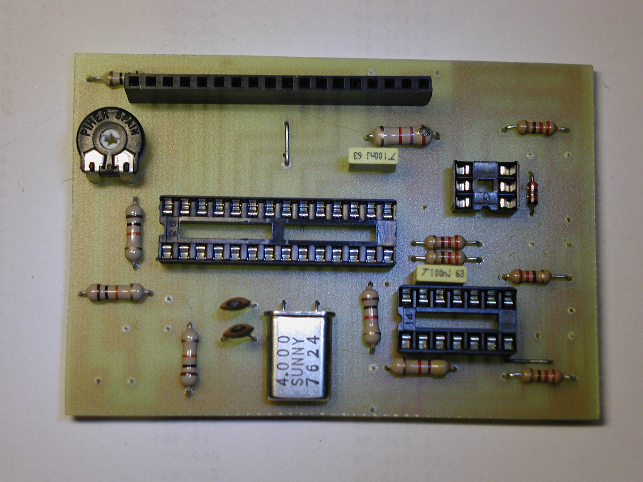
Fig. 8: Floriano's circuit, before the final assembly.

Fig. 9: Floriano's circuit, assembled.

Fig. 10: Another picture of Floriano's circuit.
Max Marenghi
In February 2013, Max sent to me some photographs of his circuit and autorized me to publish them on the site. Max has put his circuit in a box quite similar to mine and he is using it in his studio. While discussing about the splitter, Max suggested that it would be nice to show the routing table in some way, instead of just "Splitting..." while the circuit is working. I think it is a good idea, I hope to find the time to implement it someday!
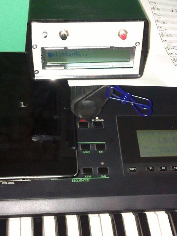
Fig. 11: Max's circuit.
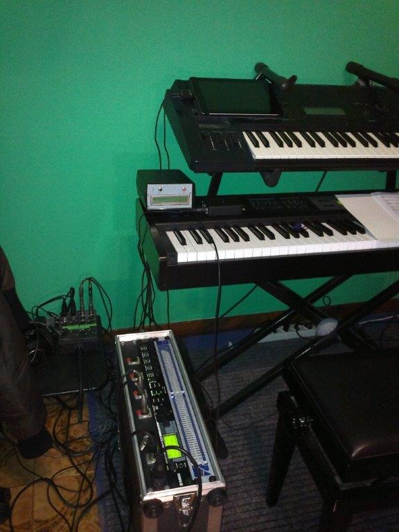
Fig. 12: Another view of Max's circuit.
A possible improvement
By discussing with Floriano, we understood that this project might be considerably expanded, controlling more than just two outputs. Everything can give a sort of "MIDI patch bay", able to deliver messages on several different physical outputs depending on which logical channel they are sent. To learn a little bit to use Eagle, I played a little with the concept and I tried to route the PCB, even if I never built it.
Here is the complete archive containing this project, as it is. There is a double side PCB, quite dense (the minimum clearance is 10 mils) and which probably needs to be debugged. If you want to try it (at your own risk), let me know how it went. Always use the HC series for the logic gates, so 74HC245 and 74HC00. I added some LEDs, to indicate the MIDI activity on each output and on the input.
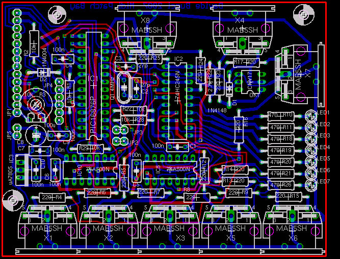
Fig. 13: The MIDI patch bay project, a view of the double-sided PCB in Eagle.
The board is small enough to be modified by the free version of Eagle. This means that you can modify the schematics as well as the PCB as you want. You can correct the errors that might be present in my design. I would be happy to be kept informed if this stuff works, since (I have to insist on that) I did NOT build this board and so it is untested. The PIC assembler file for this version of the circuit is contained in the archive. You can if you want use it for the base version of the circuit by changing the number of the outputs from 6 to 2 in one of the first definitions in the source code. Feel free to modify this project as you wish.
Conclusion and acknowledgements
Even if I have long wanted to explore the hardware part of the MIDI protocol in order, the idea from which everything started came from fruitful discussions with Daniele and Sebastiano, in the Nuova Elettronica forum. Sebastiano asked something slightly different and Daniele and I answered to his help request. From that, several interesting exchanges followed, about USART, software organization as well as the general project architecture.
2026 addendum and the firmware v. 2.1
It is fun to read again this page that I wrote about twenty years ago. At the time I needed to split my MIDI interface between my digital piano and the Proteus/2. It turns out that as of August 2026, I still own and use both instruments. I haven't used very frequently the MIDI patch bay since having updated the firmware in 2007. In fact, I haven't recorded much music between 2007 and 2022, but since then I have created again a small home studio and I am using MIDI much more frequently now.
Above, I mentioned "Nuova Elettronica" and its forum. Needless to say, the legendary Italian hobby electronics magazine no longer exists, and neither does its forum, which I frequented from around 2003 until it closed.
When I tried to use again the MIDI patch bay, I noticed two problems:
- The display was damaged. I already knew this! While working on the project, in 2005 I zapped some lines of the display driver because of a wire that touched it while being carrying 30V from a power supply I was putting together. The defect and the missing lines are visible in the above pictures, which I took in 2005.
- The display sometimes did not start up properly and remained in a single line configuration that is the default of the HD44780 LCD display driver.
Therefore, after having bought another PIC16F876 (the original one was long ago being reused in another project), I first managed to find a new LCD display. Then, I noticed that the second problem was even more present and updated the firmware. I have used several times HD44780 LCD displays with PIC projects and I have an initialization procedure that is more robust.
I also changed the strategy for controlling the contrast of the LCD display. Back in 2005, I wanted to see if it was possible to change it using a PWM signal and I added the circuit using the NPN transistor, the two resistors and the capacitor around the pin 3 of the LCD. Now I think that it is easier and more efficient to just use a single 10 kΩpotentiometer, put between 5V and GND with the wiper connected to pin 3.
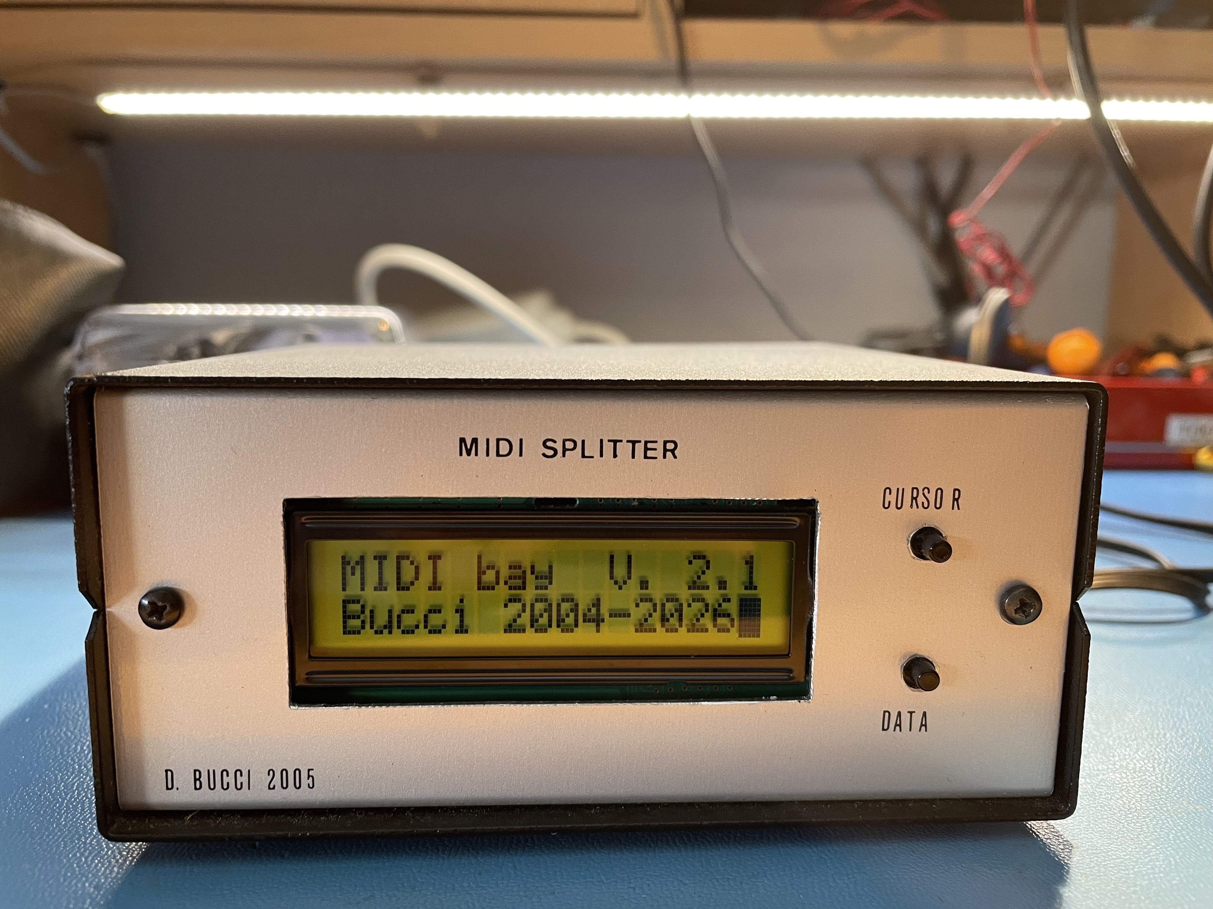
Fig. 14: My MIDI patch bay, with the new display.
Grazie mille!Of course, if you have some comments or if you would like to send some photos of your realization, you can write to me using the email address: davbucciNoNsPaMmArE@tiscali.it, removing of course the NoNsPaMmArE part of the address.
Log:
- 14 August, 2026 - Updated the page: corrected bad encoding for accents in the Italian version of the page, added the 2026 addendum. Updated the firmware to version 2.1. Added this log.
- 2 June, 2013 - Typos corrected.
- 2 February, 2013 - Added the pictures of Max's version of the circuit and the note. English translation of the page.
- 6 July 2008 - Version 2.0 of the firmware, with a maximum of 6 outputs.
- 2007 - Updated to the new graphical style of the website. Added the version 2.0 of the firmware
- March 2005 - First version of the page.
 License:
 --------

    Copyright (C) 2005-2007  Davide Bucci davbucci at tiscali dot it

    This program is free software; you can redistribute it and/or modify
    it under the terms of the GNU General Public License as published by
    the Free Software Foundation; either version 2 of the License, or
    (at your option) any later version.

    This program is distributed in the hope that it will be useful,
    but WITHOUT ANY WARRANTY; without even the implied warranty of
    MERCHANTABILITY or FITNESS FOR A PARTICULAR PURPOSE.  See the
    GNU General Public License for more details.

    You should have received a copy of the GNU General Public License
    along with this program; if not, write to the Free Software
    Foundation, Inc., 675 Mass Ave, Cambridge, MA 02139, USA.