A wall clock with PIC16F84 and PCF8573, second part
Introduction
Circuit description

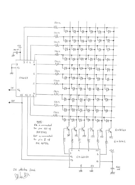
The first CD4017 counts from 1 to 10 acting on the rows of the matrix. Each time it starts again, a carry on pin 12 is used to increment the second CD4017 which controls the selected column. The two counters are held in the reset state when needed by the microcontroller to synchronize the count with the clock.
In the schematic, I have drawn all the 60 leds, but in my case only 48 green leds are controlled by the circuit. In fact, 12 red leds are always on and indicate hour positions. This way, the sequence to be respected in the circle is 4 green leds followed by 1 red led and so on. The whole clock with the 60 leds absorbs around 300 mA.
Changes to the firmware
If you already built the PIC16F84 and PCF8573 clock and you downloaded the ASM file described in the first part of the project, you already have all you need for controlling the leds. The code already handles the reset of seconds counter every minute.
Notes on the look of finished circuit
Once you build your wall clock, you will probably want to put it in your living room in a very visible spot. To do so, the most critical problem an hobbyst has to solve is how to fabricate an aesthetically pleasing enclosure to avoid spoiling all the hard work done on electronics. It is not easy to find a solution being at the same time easy to build and good-looking. Here I say a few words about the solution I found, hoping it will inspire you in some way.
I used a polystyrene transparent panel, sprayed with a glossy black paint to make it become half-transparent. The best way to proceed is to cut the panel to the wanted size and then spray the paint on a single side, trying to obtain an uniform layer. In my case, I opted for a panel thickness of 4 mm. I obtained good results with acrylic black paint diluted and sprayed by an compressed-air spray gun. Varying the dilution, you can adjust the transparency. Polystyrene is a low cost and easy to work material (much easier than PMMA, also known as Plexiglas). You can find it in a lot of DIY stores.
The circle made by the 60 leds can be then assembled on a second polystyrene panel (smaller, in my case I chose a square size of 19 cm x 19 cm). Inside the second panel, the circuit is installed in a rectangular aperture. This way, displays mounted on the circuit will be very close to the front panel, if you paid attention not to put very high parts around them.
The smaller polystyrene panel can be drilled to hold the leds in place and they can be fixed with super glue. I made all the electrical connections on the leds with a 24-pins flat cable which is then connected to the main circuit with a connector. In this way, the connections are kept relatively neat (you can easily do a mess with the 60 leds). You can easily separate the circuit from the leds, too.
If you can and want to build a PCB, you can put the leds in circle in the circuit itself, on a single neat PCB. This will ease considerably the wiring.

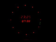
A photograph of the first prototype, working.
To keep everything together, I glued the head of small screws on the front panel and then attached the circuit to them. The second panel is in this case kept in place with a sandwich-like construction. If you like it, you can enclose everything in a box or leave the circuit accessible. Remember that you need to let accessible the two push buttons to set date and hour.
 License:
 --------

    Copyright (C) 2004  Davide Bucci     davbucciPleasenospamherE@tiscali.it

    This program is free software; you can redistribute it and/or modify
    it under the terms of the GNU General Public License as published by
    the Free Software Foundation; either version 2 of the License, or
    (at your option) any later version.

    This program is distributed in the hope that it will be useful,
    but WITHOUT ANY WARRANTY; without even the implied warranty of
    MERCHANTABILITY or FITNESS FOR A PARTICULAR PURPOSE.  See the
    GNU General Public License for more details.

    You should have received a copy of the GNU General Public License
    along with this program; if not, write to the Free Software
    Foundation, Inc., 675 Mass Ave, Cambridge, MA 02139, USA.
