
A 55 W + 55 W power stereo amplifier based on ESP P3A
Electrical schematics and PCB
Realisation
Measurements
Loudspeakers
Distortion (june 2014)
Conclusion
Introduction
I did not have a system for listening to music with an acceptable quality, an so I thought it was time to do something for it. After 25 years I am interested in electronics, I decided to make the power amplifier by myself, because it would be the fist time I make something similar and it was a good opportunity to get a little bit of experience on those systems. I was greatly inspired by the P3A project, from Rod Elliott:
http://sound.westhost.com/project3a.htmI made a small change to the input stage, using a current mirror as an active load for the differential pair. In this article I will briefly describe the wiring diagram, I will show pictures of my circuit and I'll provide some comments on the measurement results.
Circuit diagram and PCB
Here is the circuit diagram I used for my amplifier:
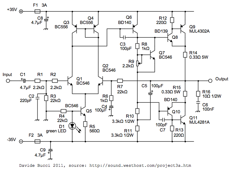
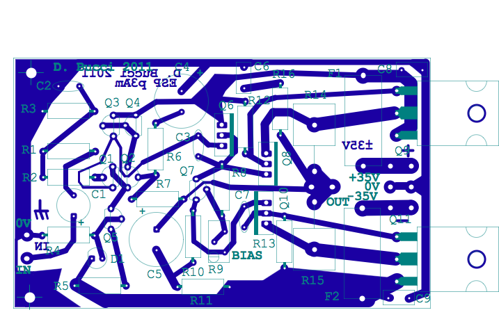
If you want, here is the source code of the schematics, available in the FidoCadJ format. I thought I would have to adjust the compensation network and in particular the value of the capacitor C3 to ensure the stability of the circuit. This was due to the fact that the open loop gain was modified thanks to the current mirror. This has not proven to be necessary. Rod Elliott sells very good printed circuit board for his P3A, but in my case, due to the small changes I made and the fact that I needed PCB's which fit in the box I found, I made my own ones (the file in the FidoCadJ format is available here). If you prefer, I have prepared a few PDF exports of the relevant layers of the PCB.
To understand the behaviour of the circuit, I strongly suggest a reading of the original article by Rod Elliott (note that the names of components change from my version). I just remind here that the circuit is basically a differential amplifier where Q1 and Q2 form a differential pair, driven by Q5 which operates as a current generator. Q3 and Q4 are a current mirror and transistor Q6 adds its contribution to the open loop gain. Q7 is used as a "Vbe multiplier" and takes care of the proper bias of the output stage, built with two Sziklai pairs. C5 is the bootstrap capacitor, useful for increasing the gain of Q6. The stability of the circuit is provided by the Zobel network C6 and R16, together with capacitors C3 and C7.
Making
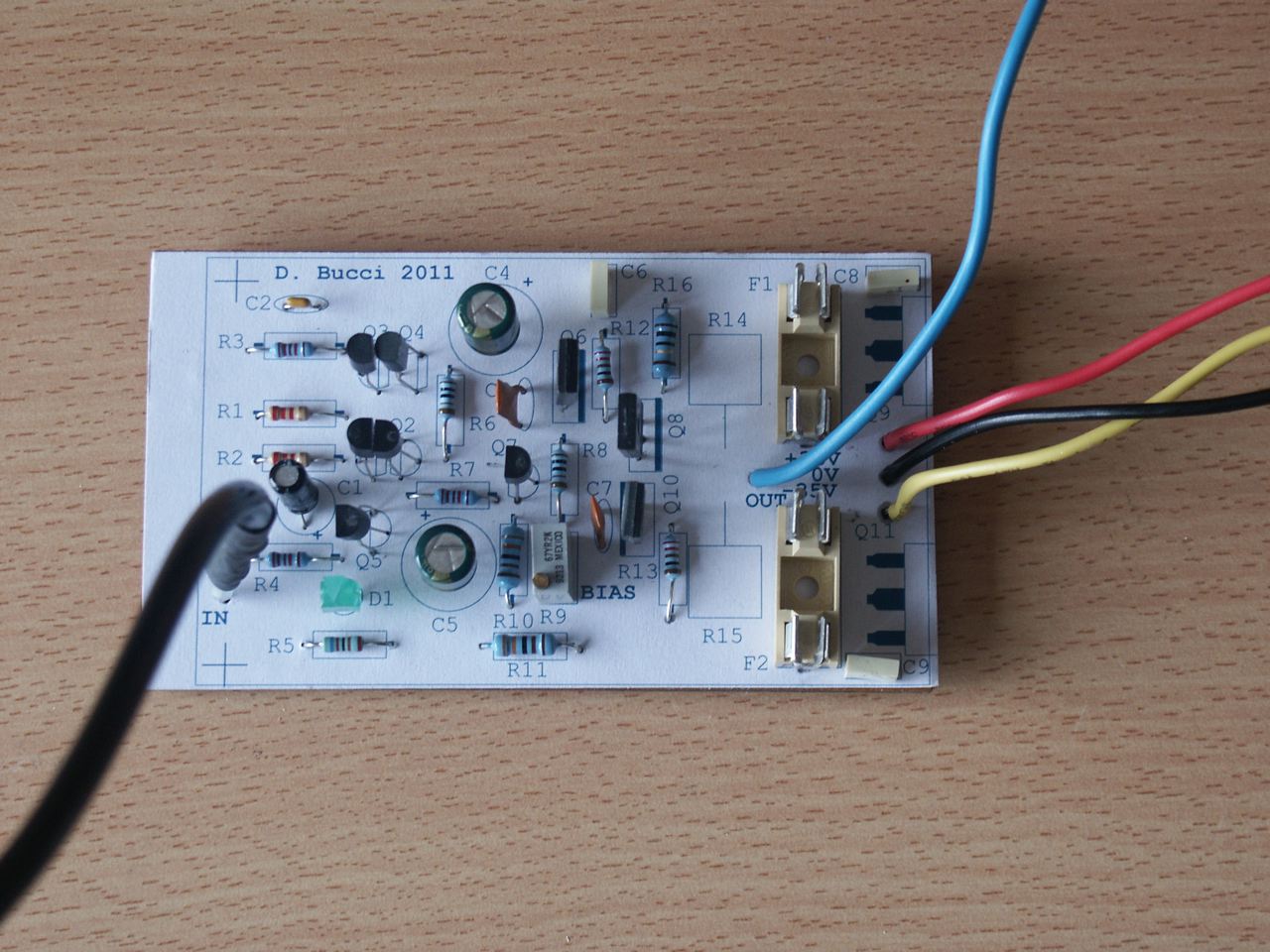
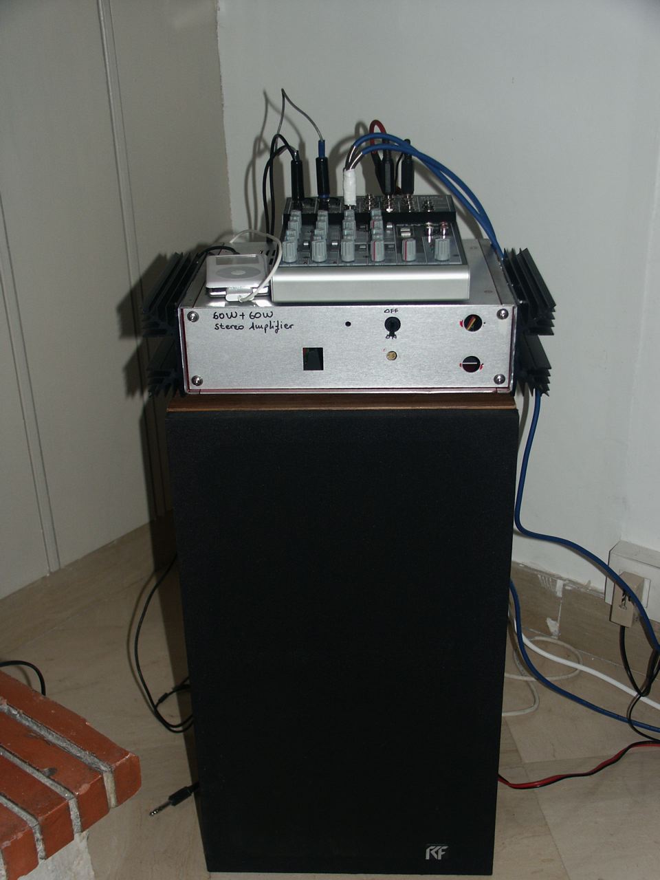
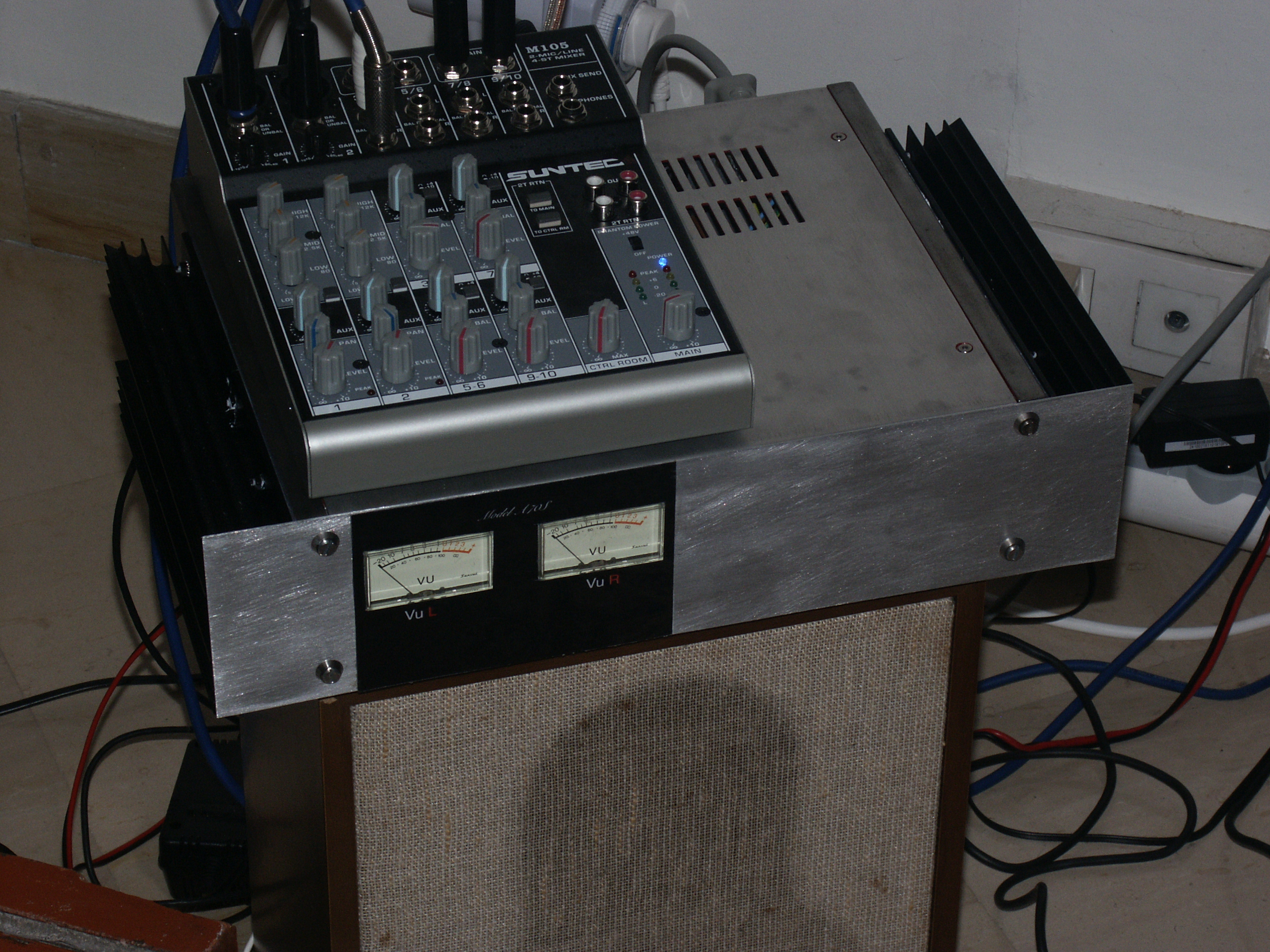
Above, a picture with almost all components installed on the PCB. Probably, the change I did does not improve significantly the performances of the circuit, but I wanted to test this configuration anyway. If someone wants to fabricate the circuit, I think it may be better to adopt on the configuration suggested by Rod Elliott and base the work on his PCB's. I also suggest to follow Rod's procedure to test the project P3A and regulate the bias point. The most important things is that the adjustable resistor (R9 in my circuit, VR1 in Rod's) must be set in the position of maximum resistance before giving power and the speakers should NOT be connected before the circuit has been tested carefully. The bias current used in my circuit gives a voltage of 50 mV between the collectors of Q9 and Q11 without signal at the input of the circuit. Here is against the amplifier mounted in the box with the small mixer that I use as a pre amplifier. The configuration is not definitive, also for what it concerns the front panel. I have to see how to make something aesthetically acceptable.
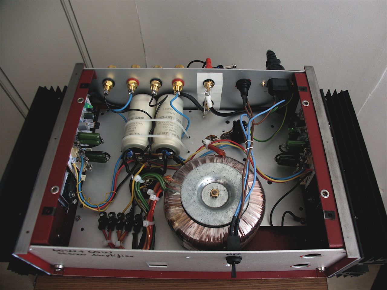
Here is a view of the inside of the amplifier. I would like to block the wiring with plastic cable ties, but for now some connections are free since I still need to decide for the final configuration, tracking all the ground loops and so on. I would also like to include a protection for speakers.
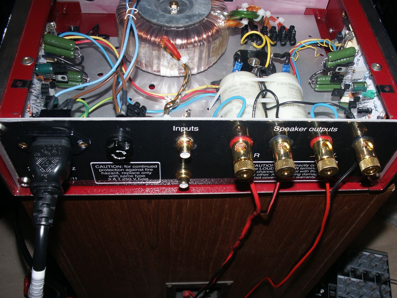
I mounted on the sides four heatsinks, each one given for a thermal resistance of 1.4 K/W. These heatsinks would probably work better placed vertically, but I had to put them horizontally to fit in the place I had. Here is another image of the inside of the amplifier, where we can see the speaker connectors and the input RCA connectors. The writings are inspired by the back of an old Marantz amplifier from 1970s.
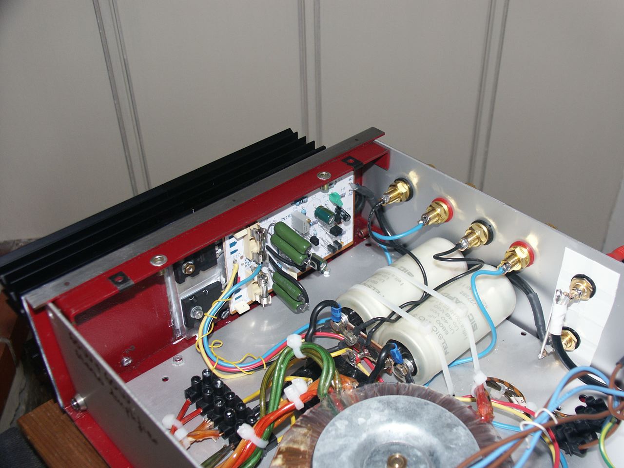
A view of the filter capacitors, the circuit with the power transistors mounted on the heatsinks. At full power, on the edge of the clipping of a sine wave, I measured a power of 52 to 54 W average per channel on 8 ohm load. The heatsinks are designed to handle this without problems for hours, but I think this event will not happen very often, at least for the respect I owe to my neighbors! I do not have a measure of distortion, it is something that can not be appreciated on the oscilloscope, but I instead paid a lot of care to avoid self-oscillation.

Measurements
Once completed the amplifier, I was curious to measure the most important characteristics. Right now, I'm not equipped to measure the distortion, but nevertheless I wanted to measure the maximum power delivered to a load of 8 ohms. First of all, so I built a dummy load by putting in parallel 7 resistors 56 ohm and able to handle 10 W each. Although in theory the maximum power is about 70 W, the resistors get very hot when it is over 30 or 40 W. They do not seem to suffer from temperatures above 100°C. The two pictures below show the output signal with a sinusoidal excitation, the first one at the limit of clipping and the second case with an evident one. The maximum power at the limit of the clipping is between 52 and 54 W on average for a sinusoidal signal. The circuit could provide a few watts more without problems, by slightly increasing the voltage. In my case, I used a transformer that provides 24 V + 24 V, which means that I get a little less than 35 V + 35 V nominal.


The circuit has worked pretty well from the very beginning, but I had to increase the value of capacitors C8 and C9 from what was originally planned (100 nF). This prevented self-oscillations that appeared when I pushed the amplifier into double figures watt power. To avoid overheating, I tested the amp at full power for more than an hour. Heatsinks become hot, but you can still put a hand on them or on the power transistors without burning your skin.
Distortion (june 2014)
I was able to perform some distortion measurements thanks to a Brüel & Kjaer 2034 double channel signal analyzer adopting a Hanning window. It is useful to have a look at the distortion when trying to measure the maximum output power that the amplifier can give, as well as the type of the distortion. In fact, the oscilloscope analysis is not very reliable, since it is difficult to appreciate at the screen even a moderate amount of harmonic distortion.
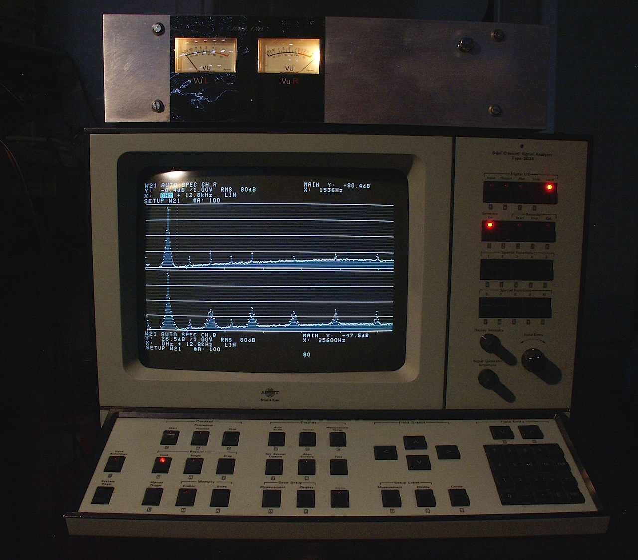
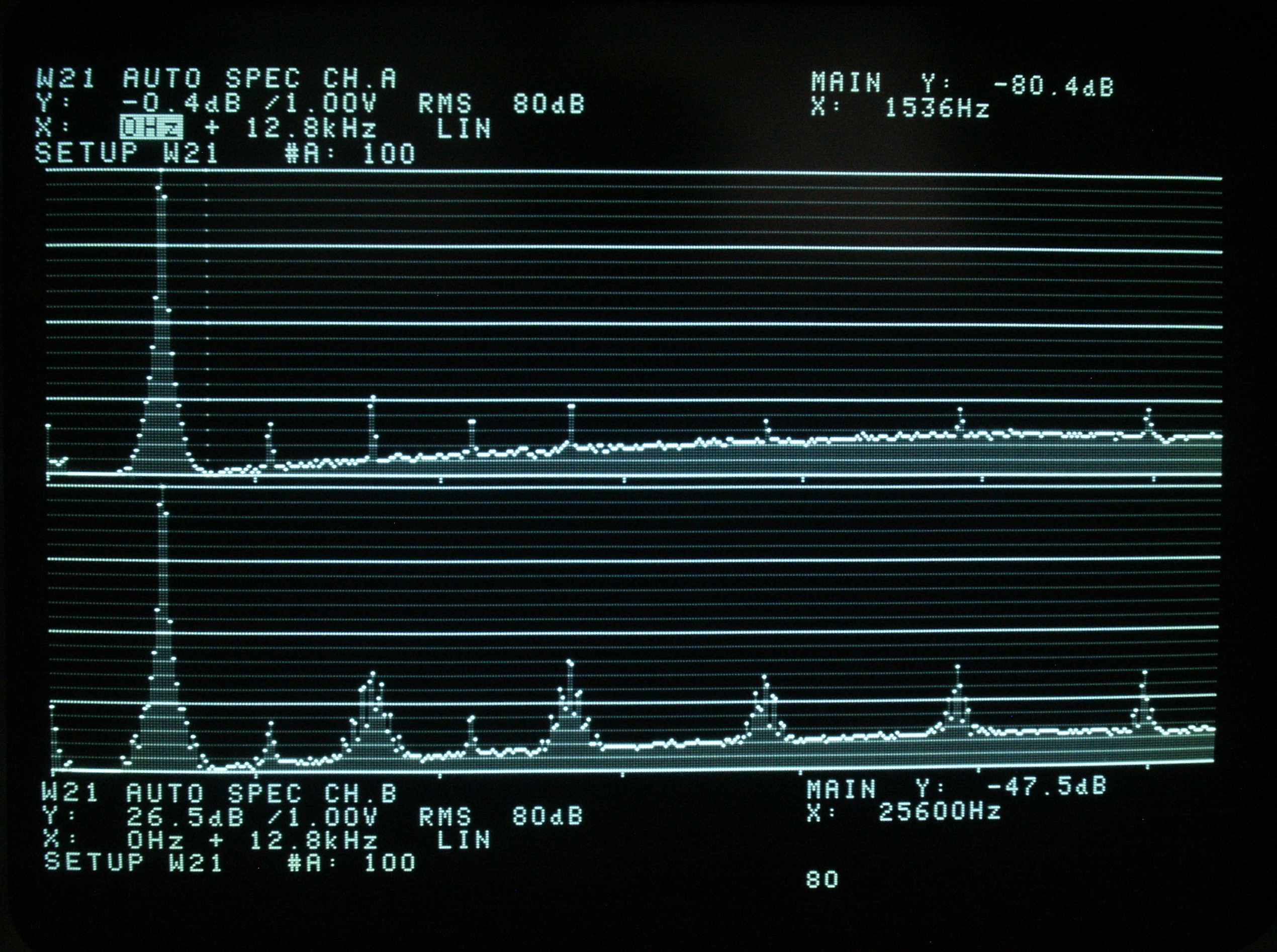
Therefore, I fed the amplifier with a 1 kHz sinusoidal signal (whose THD is about 0.4%) and adjusted it level in order that the output distortion on a 8.1 ohm dummy load reached about 1%. The RMS output signal amplitude was 21.13 V, corresponding to 55.8 W. The upper track of the analyzer's screen shows the spectrum of the input signal. The lower track is the spectrum of the signal on the load. It is interesting to notice that the distortion is mainly on odd harmonics, and that their line width is greatly increased. This effect is due to the 100 Hz modulation due to the ripple on the power supply rails which leaks on the output load only when the amplifier is clipping the output signal. In normal operation, the amplifier is very quiet and the THD is not measurable with my current setup (I would say it is probably below 0.1%).
Loudspeakers
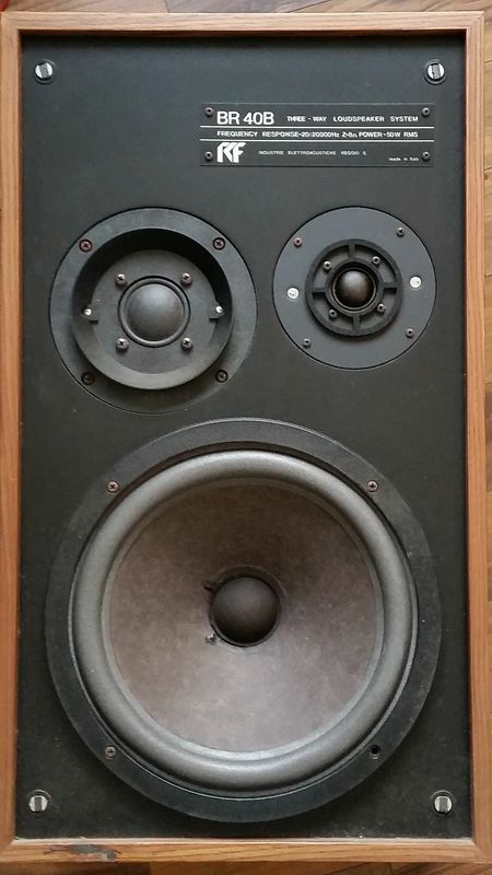
We can see here by the damage made by the time on the speakers that I would like to use with this amplifier. RCF is an Italian brand, the quality of this model, from what I understood, was average/good, hence my interest to attempt a repair. I would like to repair the speaker myself, if I will be able to find a "foam" of the right size (this has been originally written in 2011, look below!)
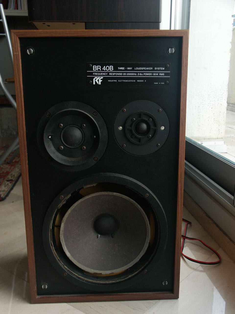
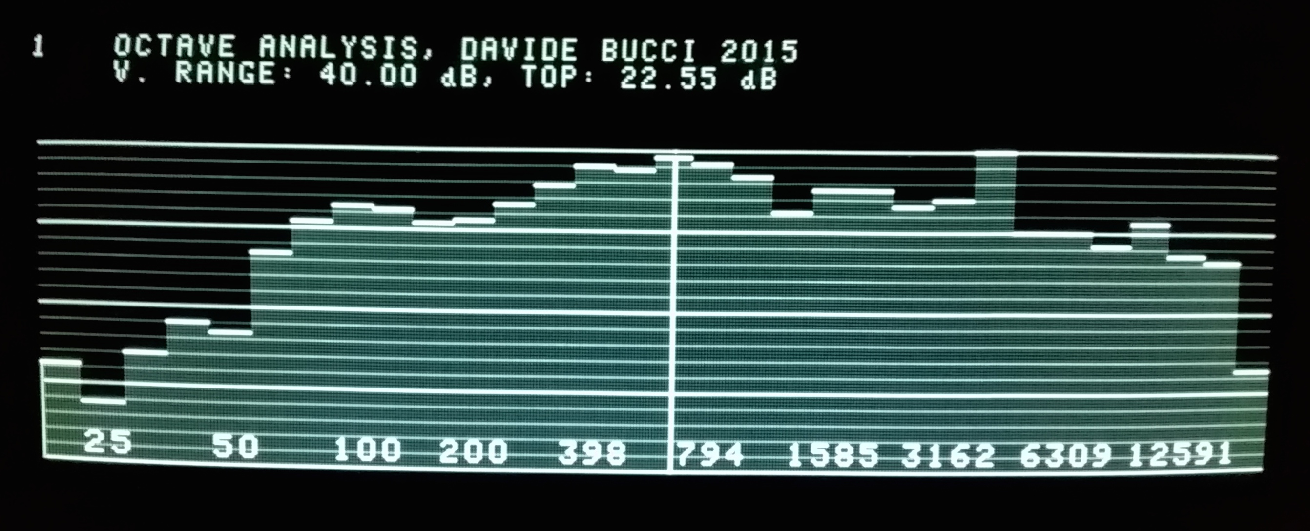
In January 2015 (times passes by!), I was able to find the new foams and to repair the loudspeakers. I also had to change some of the absorber that was used inside the midranges. I tweaked the response a little by employing an L-pad, to improve the sonic response in my living room. Now, I am pretty happy about the overall result and I can confirm that the quality WAS indeed pretty good! Below there is a 1/3 of octave characterization of the loudspeaker (the one I use for the L channel), acquired with a Sennheiser e845 microphone (which is for singing, not for measurement, but gives an idea). I wrote the GPIB software for computing the 1/3 of octave measurements from the B&K 2034 spectrum analyzer, it is freely available on GitHub under GPL v.3 license.
Conclusion
I described in this article my audio power amplifier based on the project by Rod Elliott P3A. I described the circuit and the changes I did to the original project, showed pictures of my circuit and I provided some measurement results. The amplifier can deliver a maximum power of between 52 and 54 W average on a sine wave. I was very pleased with my first audio power amplifier. The circuit proposed by Rod Elliott is very effective and reliable. The maximum power deliverable by the system turns out to be slightly less than 60 W + 60 W which was my first objective, but it is still exceeding my needs. The reason for this does not come from the amplifier circuit itself, but rather the fact 3 or 4 V are missing from the power supply output.
Log:
- December 30, 2022 - Corrected some typos, reordered the log.
- March 2015 - Info about RCF BR40b repair, PDF files of the PCB added.
- June 2014 - Distortion measurements added.
- 2011 - First version of the page.