
MIDI interface for the Amiga 500
Disclaimer
WARNING: assembling such a circuit will require a certain experience in electronics. If you fry your computer or harm yourself, do not consider myself responsible for that.
Introduction
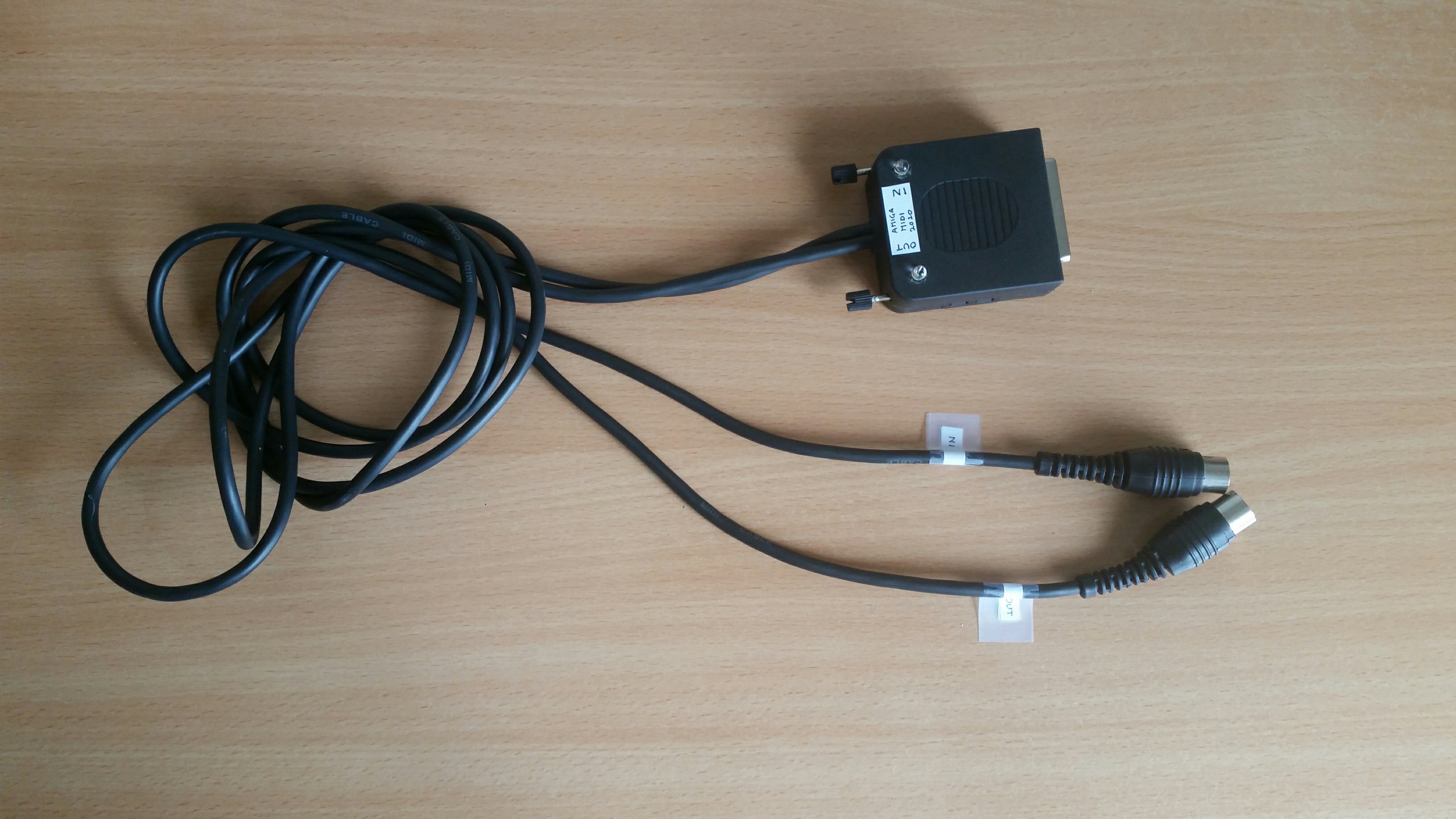
Fig. 1: The first prototype of my interface, assembled
I acquired a beautiful Amiga 500 at the beginning of October 2020 thanks to some German friends. I obviously started by playing with some games. I recalled some of them, as a friend of mine used to have it at the end of 1980's. After a while I thought it would have been to use it to record some music and to play with MIDI. I have several electronic instruments that can be controlled with this standard and I already have some experience in building small MIDI equipments.
MIDI is a standard for connecting musical instruments that has been developed at the beginning of 1980's. The Atari ST came with MIDI interface as standard and thus became the most used computer for music. The Amiga too can exploit quite effectively a simple MIDI interface.
I discovered that there were some interesting programs able to use the Amiga as a MIDI recording studio, and that at the time MIDI instruments could be attached to the serial port by means of simple interface. I searched for some schematics, but I have not been entirely satisfied of the circuits I saw. This article therefore describes the very simple MIDI interface I built, visible in figure 1. It will probably work on other Amiga models, but I saw some little differences in some interfaces for the Amiga 1000 that will require some modifications.
I will start with a brief description of the circuit, then I will comment how I built my prototype.
Circuit diagram
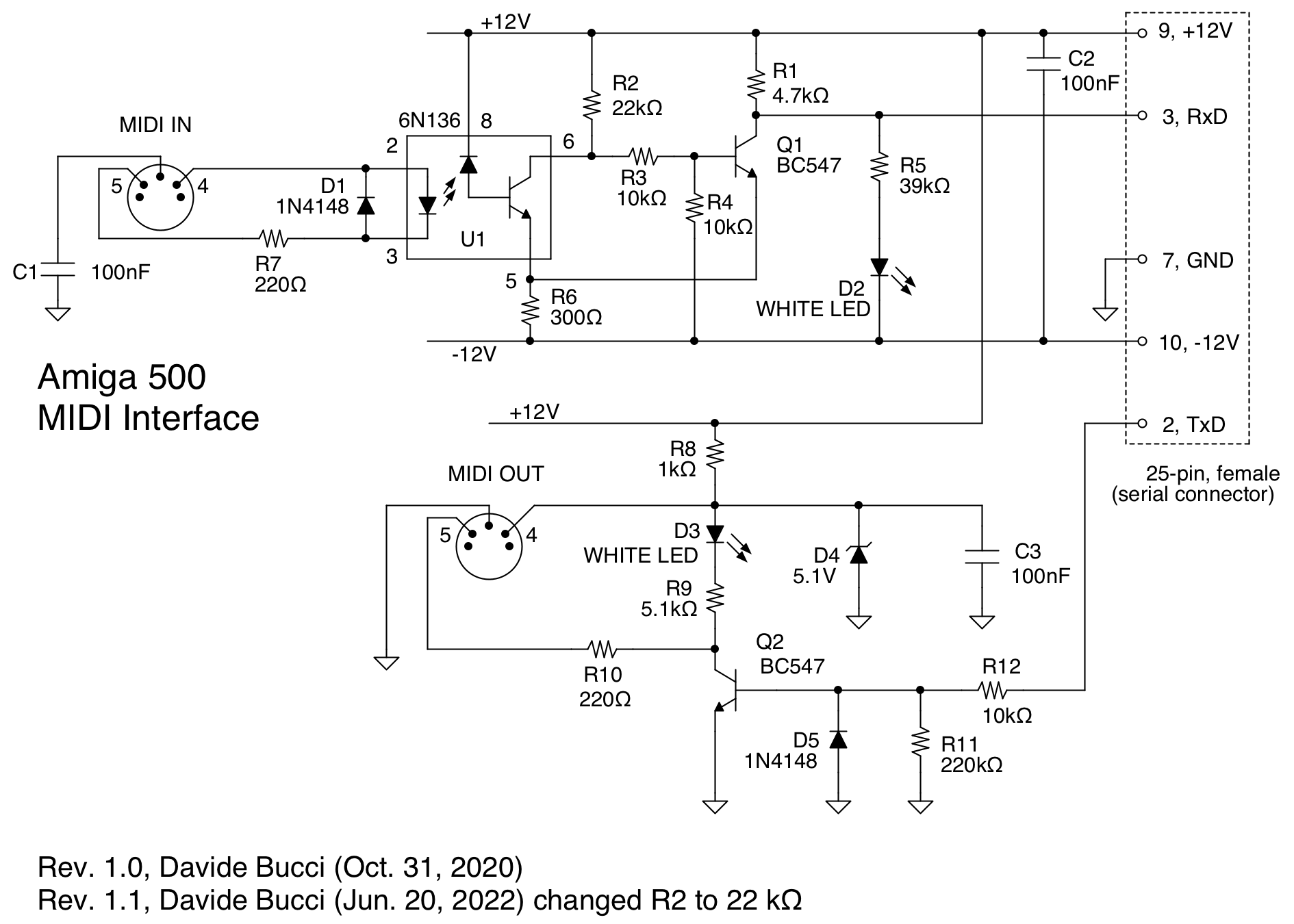
Fig. 2: The electronic circuit of the MIDI interface I built for my Amiga 500
The Amiga 500 sports a DB25 male connector used for the serial port. On that connector, +12V and -12V power rails are available on pins 9 and 10 for external circuits. The RxD and TxD lines (pins 3 and 2 respectively) are instead used for the receive and transmit lines of RS232 (as per DTE convention). On the RxD line, the computer expects a voltage comprised between -12V and -3V to receive a "1" bit and a voltage between 3V and 12V to indicate a "0" bit. In the MIDI standard, they are sent at a speed of 31250 bits per second, with a start and stop bit added to each byte.
Figure 2 shows the complete circuit of the interface. Instead of using TTL logic gates and level shifters such as a MAX232 as I saw elsewhere, I built a smaller circuit using NPN transistor. Concerning the MIDI IN, the input is a relatively standard opto-isolated receiver built around U1, a high-speed 6N136 optocoupler. The output transistor of U1 is connected with Q1 so to form a Schmitt trigger circuit. It also generates an appropriate signal for feeding the RS232.
The output section is elementary, as well. The TxD signal coming from the computer is used to trigger the base of the transistor Q2. Diode D5 is used to avoid that a negative voltage on TxD entail a breakdown of the emitter-base junction of Q2. The voltage on the MIDI OUT connector is limited to 5V (as specified by the MIDI standard) by means of a simple circuit around D4, a 5.1V Zener diode.
Two moder white LED's are used to signal the interface activity, D2 corresponds to MIDI-IN and D3 to MIDI-OUT. Resistances R5 and R9 are calculated to let approximatively 0.5mA flow in each diode. Use relatively modern blue or white LED's. A classic led bought in 1987 would barely turn on with such a low current and it would certainly not have been white.
The prototype

Fig. 3: My interface, built on a prototyping board
Figure 3 shows a picture of my prototype, built on a prototyping board. I used a 2 m MIDI cable that I cut in half to obtain the input and output connectors. That's practical, as I have not yet met someone who likes soldering a DIN connector, but requires to choose a reasonable length. If you prefer, you can use two female connectors to be mounted on the circuit. This was done by many MIDI interfaces commercially available for the Amiga back in the days.
A few months ago, I found some interesting DB25 female connectors that came with a small patch board. I thought the plastic case would be big enough to contain the little circuit I boult. I glued the two LED's on the top case, along with their current-limiting resistors R5 and R9. I also put two labels on the MIDI cables to identify IN and OUT.
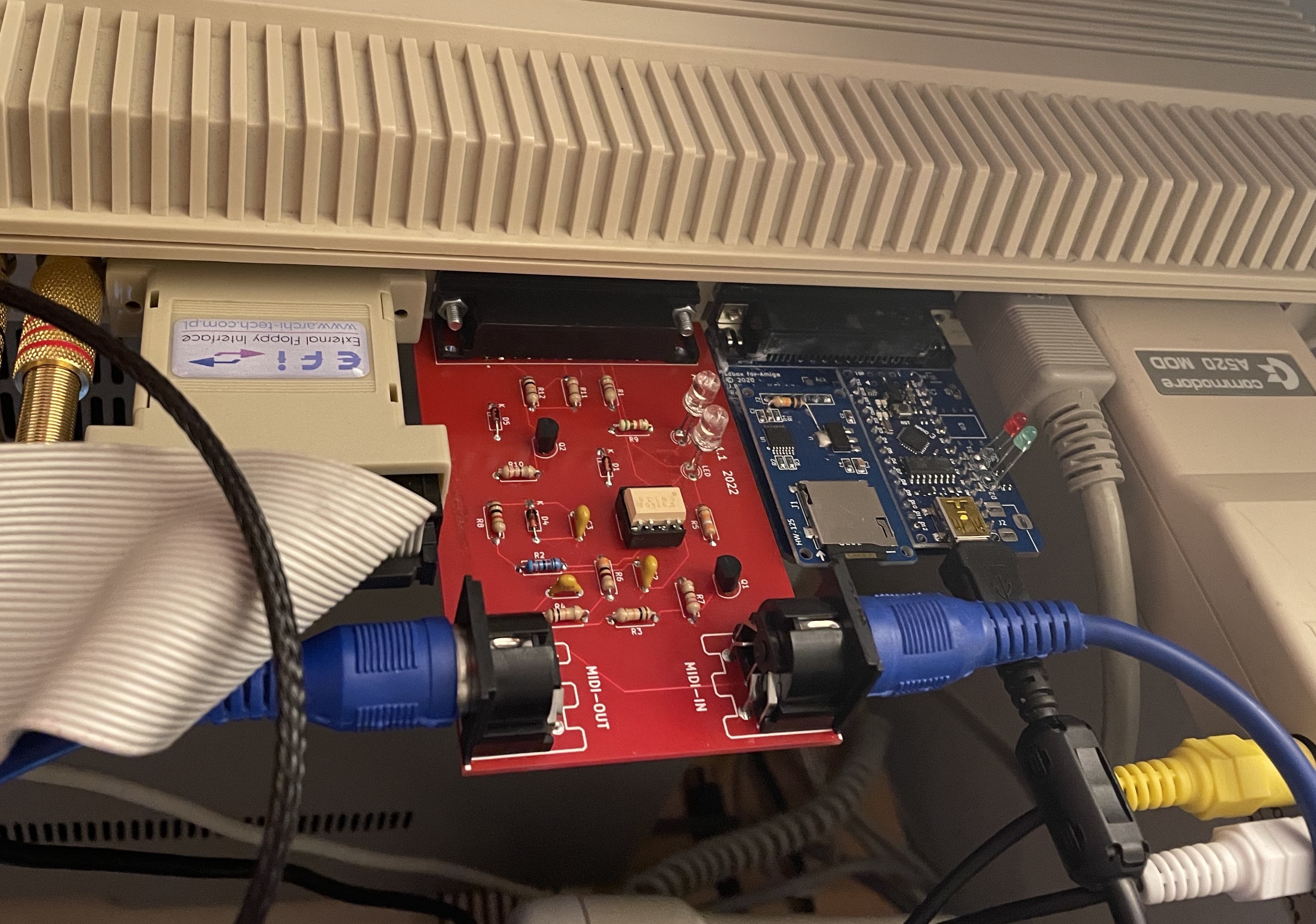
Fig. 4: Marcello's PCB on the crowded back of my Amiga 500.
UPDATE 2022-June-21: I got in touch with Marcello Messora, who prepared and built a nice PCB. He was able to use the MIDI OUT immediately, but the MIDI IN refused to work. Long story short, changing R2 from 10 kΩ to 22 kΩ fixed everything! Marcello put the PCB project files here.
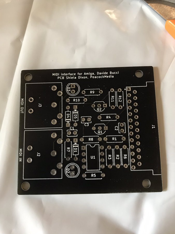
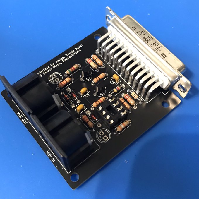
Fig. 5: Shiela version of the PCB. The orientation of the DIN connectors is more fit to crowded Amiga's.
UPDATE 2022-December-22: Shiela Dixon tried the interface, liked it and decided to draw another nice PCB for it. Fig. 5 shows it.
Conclusion
I had some fun assembling this little MIDI interface, that is in practice a simple level shifter with an opto-isolated input. It took a Saturday afternoon, worked first time and allowed me to record some music with Steinberg Pro-24 and Music-X on my Amiga 500 as visible in figure 5. It has been a fun project and I am sure I am going to use it often as using those Amiga programs has a certain charm of its own.
Of course, if you have some comments or if you would like to send some photos of your interface, you can write to me using the email address: davbucciNoNsPaMmArE@tiscali.it, removing of course the NoNsPaMmArE part of the address.
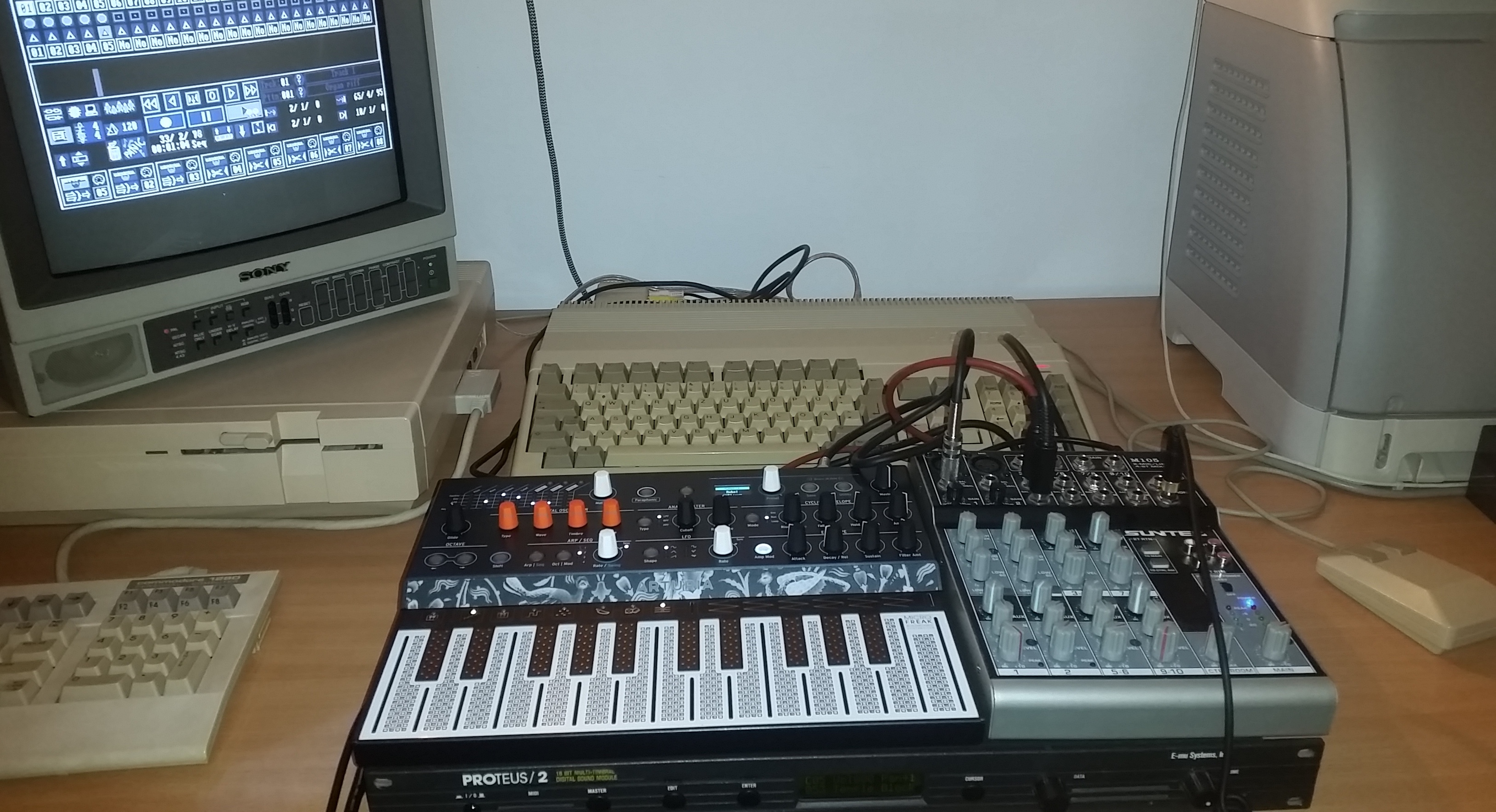
Fig. 6: Rocking MIDI with Amiga!
Page log:
- December 22, 2022: Added Shiela Dixon PCB.
- June 21st, 2022: Added link to Marcello Messora's project. R2 tweaked to 22 kΩ
- October 31th, 2020: first version of the page, in English.

Cet oeuvre est publié sous une Licence Creative Commons.