
Repairing my Commodore 64
Introduction
My first computer was a Commodore VIC20 that my mother bought second hand in 1985. I liked it a lot, but quite rapidly I realized that there was something much more powerful around, called Commodore 64. For example, during the 1980s, in Italy, it was still relatively difficult to find software and games. For a certain period, the only way to get something affordable to run on the computer were magazines, sold with cassettes containing a compilation of games. I remember that my late father once bought a game thinking it was for the VIC, where it was instead for the C64. Gosh! The screenshots looked amazing!
While I continued to have a particular fondness for my VIC, at one moment I recall a certain number of friends owned a C64 or an Amiga. My family then bought a 286 PC in 1991, and I could source a very nice C128D in 1994 that I still have today. Even if I could spend many hours programming in the C64 mode on the C128D, I never got a proper C64 myself until more than 30 years later, in November 2025.
This page describes how I could acquire my first C64 40 years after my VIC20 and how I could repair it. It was a tricky repair and I would like to warmly thank @root42 who very patiently gave me useful advices about the repair on Mastodon as well as Jan Beta who published a repair video that greatly helped me recognize a red herring in my analysis and interacted with me on Mastodon, too. You can read this discussion on Mastodon, if you are interested. This article is quite long, because I wanted to summarize all the information that was useful for me and that I found a little scattered in many places.
The auction
I sometimes like looking for old computers on a well-known auction website and I stumbled on a very interesting offer of a Commodore 64 breadbin, with a boxed 1541 disk drive and a datassette. Everything was sold as untested and for parts. I put an offer and managed to win the auction. What I paid was reasonable if at least the C64 or the 1541 were working or could be repaired. Since I have experience in electronics and I like to repair things, that was a great deal for me!
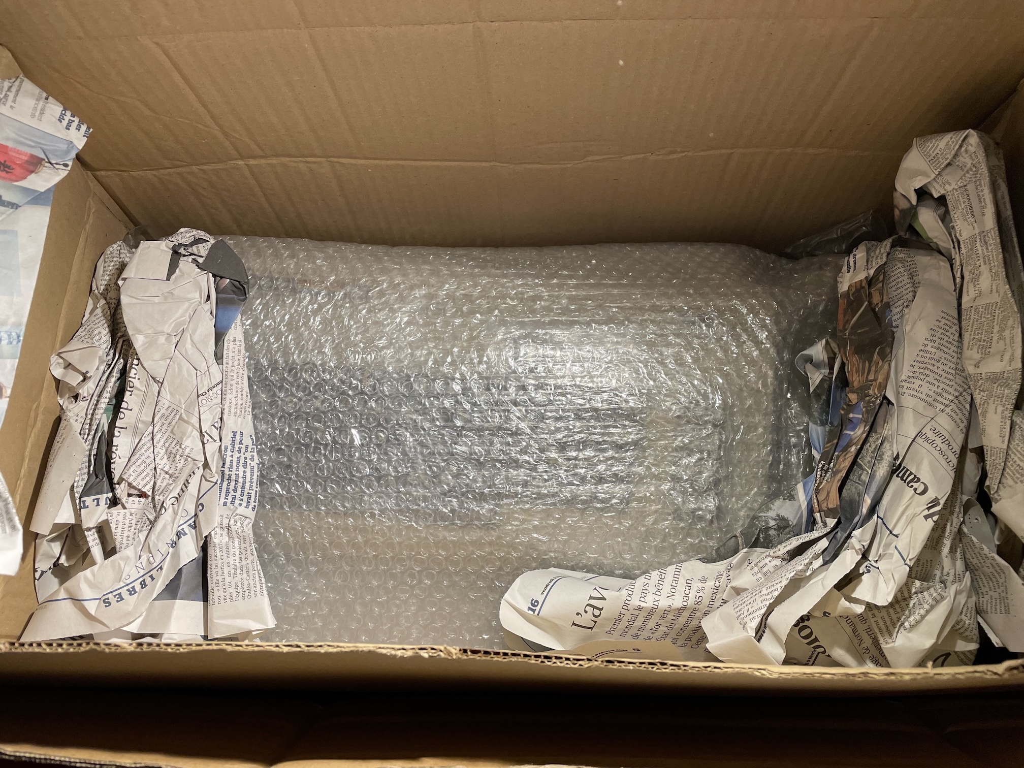
Fig. 1: The C64 appears inside the box
A few days later, I received the parcel and everything inside was very well protected, as visible in figure 1. The 1541 drive indeed came inside its box. The latter was not in a pristine condition and I may decide to try to restore it, one day or another. After an inspection to see if potential problems might arise, I had a very good surprise, testing the 1541 with my VIC20 and seeing that it worked flawlessly. I won my bet!
I then tried my first C64 and discovered instead it was not working: the classic black screen fault. You can see the computer in figure 2: it was in an OK aesthetic condition, but had a broken key (that was described in the auction) and a shock nearby. All is ready for an investigation and a repair!
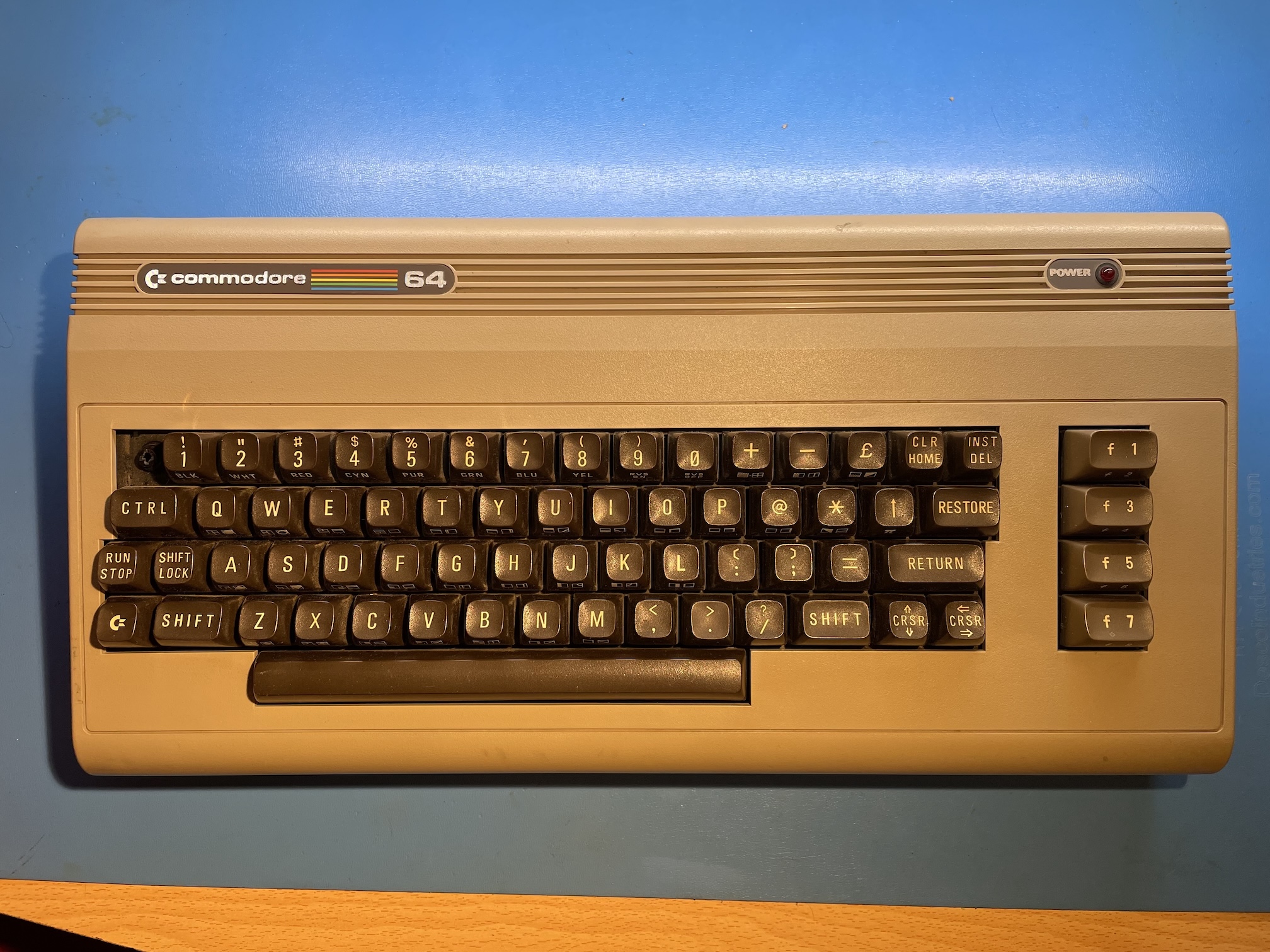
Fig. 2: The C64 had received a shock that broke the plunger of the top-left arrow key (the key cap was included of the auction, with the spring)
Repairing the C64 main board
I have a relatively well-equipped hobby electronics lab and I like to do repairs. More than the nostalgia factor, I like a lot that on 8-bit computers from the 1980s a single person can manage to know them really well. I never got the occasion to repair a C64, so I was happy to dig deeper into the hardware of this little computer that I could already explore on the software side.
I was aware that the hardware of the C64 was perfectly documented in all details and that it was possible to get spare parts at a sensible price (both original and modern alternatives). The repair announced itself as something pleasing, if not easy. Spoiler: it wasn't so easy...
I do not have time constraints for my repairs, so I wanted to take the occasion to analyze the problem and do the fix, rather than blindly swapping components. This was also due to the fact that I did not have a working C64 available.
The board revision and the easy checks
The main architecture of the C64 is built around the CPU, the video generating circuit called the VIC-II (the first version being the VIC chip of the VIC20), three ROMs, the SID. The decoding logic is contained in the so-called PLA. All revisions of the C64 are built around those custom-built chips by MOS, plus of course the 64KB of RAM and other generic chips. Commodore has produced different variants of the C64 boards that have several ASSY numbers. Mine is a NO. 250425, which is a common revision, with a simplified clock-generation circuit close to the VIC-II. Apparently, it's a version praised for a good quality of video output. Figure 3 shows an annotated picture of my board. With respect to the previous versions of the board, Commodore used a single chip to generate all clock signals instead of a more complex circuit. Beware that the position of the PLA and the SID depend on the particular version of the board. A PLA inserted in the SID socket would be immediately destroyed when power is applied to the circuit. The ASSY NO. 250425 (figure 4) is also one of the versions called longboards, because of the larger PCB with respect to the smaller and more integrated versions installed in many C64C's, called shortboards. The schematic of this version of the board are shown in figure 5.
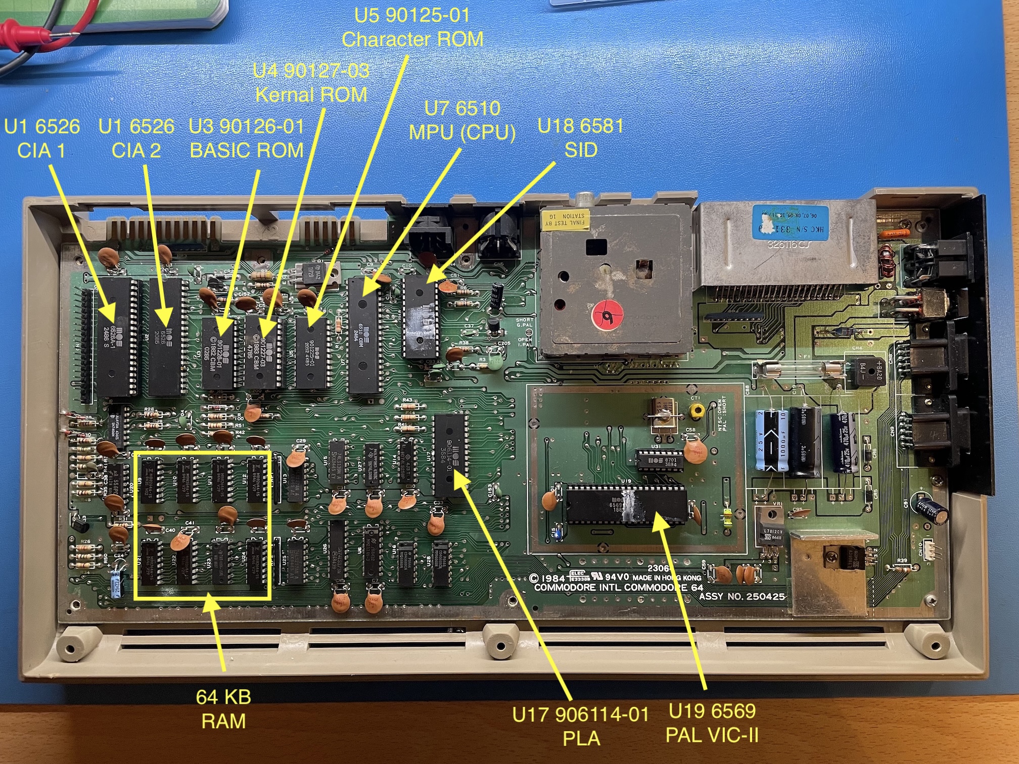
Fig. 3: An annotated view of the board of my C64. This is ASSY NO. 250425, sometimes called "version B" in the Commodore literature. Thes schematic #251469 looked to be the closest match to what is present on my board
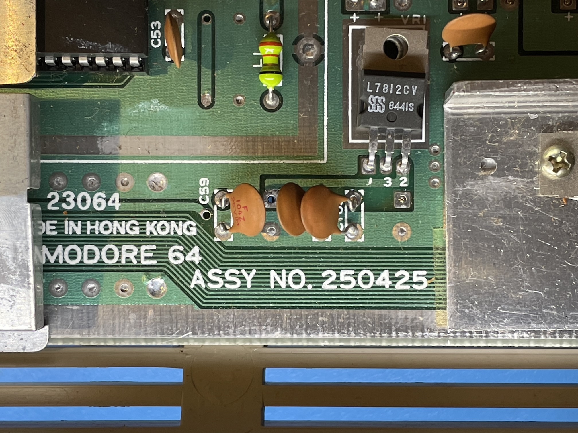
Fig. 4: A closeup of the ASSY NO. 250425, where it is visible the uA7812 regulator for the +12V DC power supply rail used by this revisions of the SID and the VIC-II.
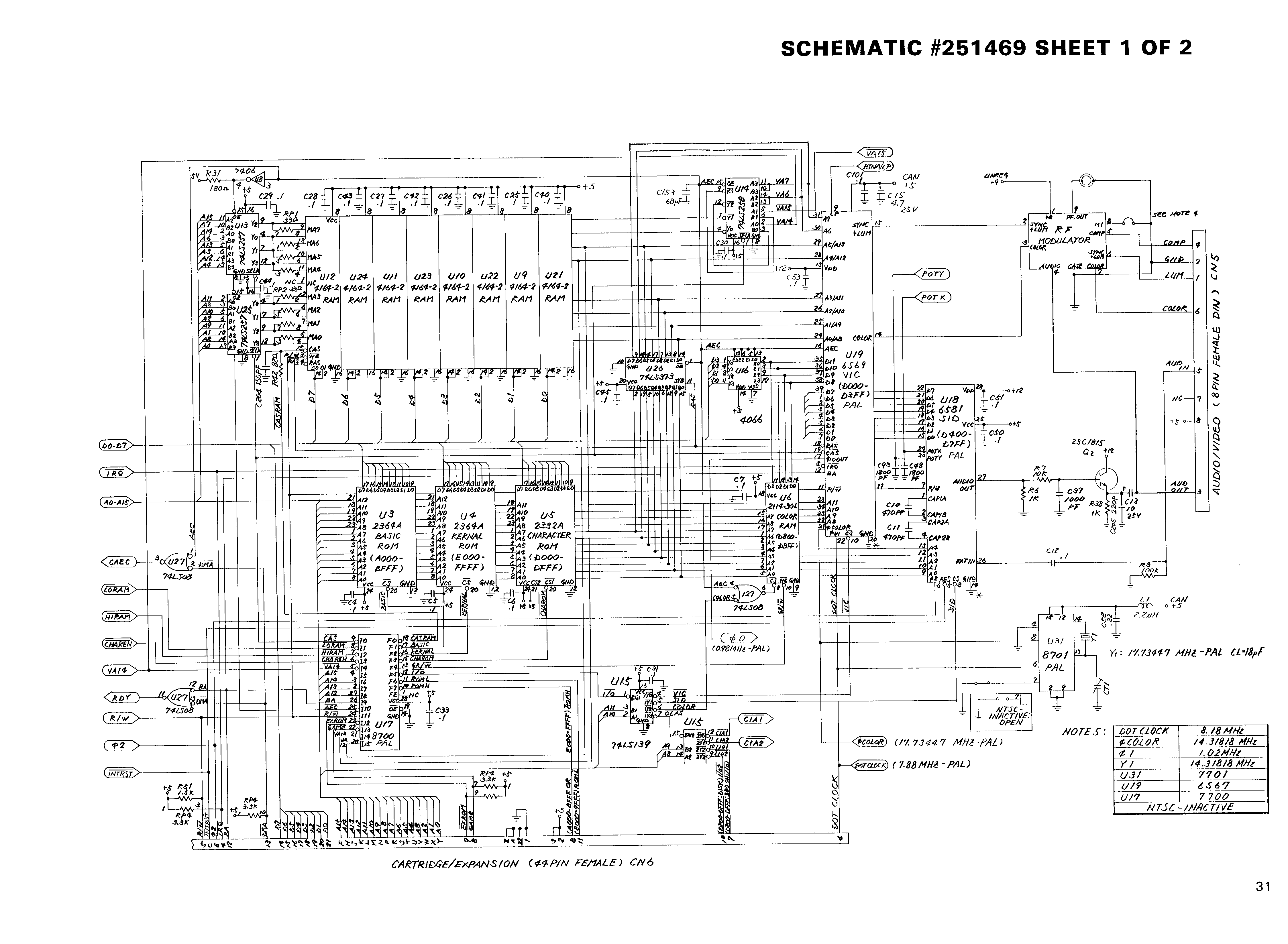
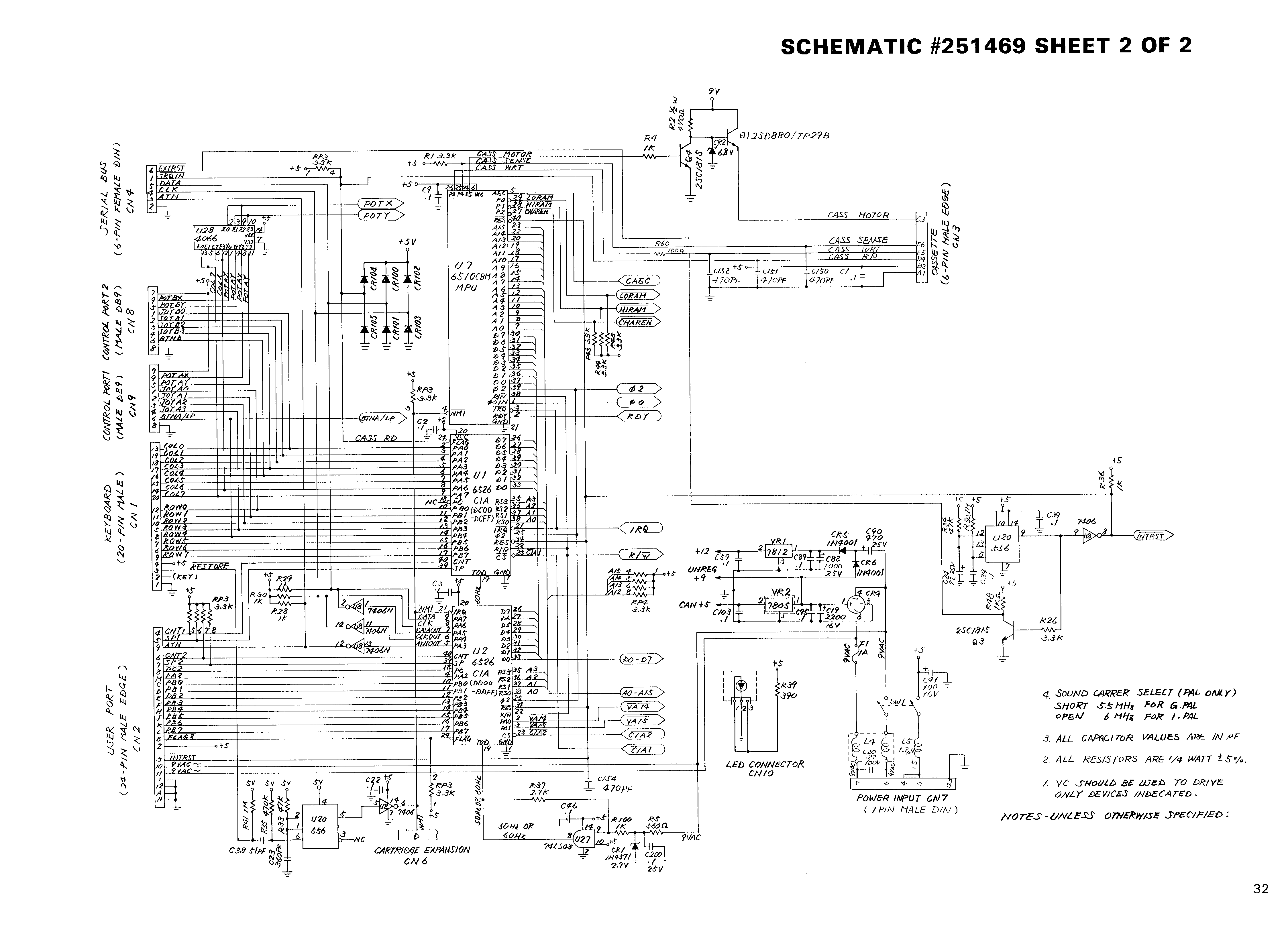
Fig. 5: The full schematics #251469 for the version ASSY 250425 (two pages, source: www.zimmers.net).
We tend to think of the CPU as the most important component in a computer. However, looking at the C64 schematics, one quickly realizes that the VIC-II controls many details, such as the dynamic RAM refresh and therefore is tightly connected to the RAM bank and other parts of the circuit. Even more than the CPU itself!
The first rule in any board-level repair I do is always to check the power supply rails. The external power supply provides +5V DC and a 9V AC through a DIN connector. The C64 has two 5 V rails: one for most of the logic circuits, which is provided by the external power supply, plus another one that is derived from the 9V AC, rectifier and filtered, plus a 7805 regulator that is used for the VIC-II. The 9V AC is also used to obtain a +12V rail for the 6569 VIC-II and the 6581 SID. An unregulated +9V DC rail is also used for the RF modulator and to power the cassette motor. A common failure point is the power switch, so it is important to check that everything is OK on this. All voltages were correct in my case. Inspecting the RAM (figures and 7) shows that the board has already been repaired at least once and there is a bodge wire.
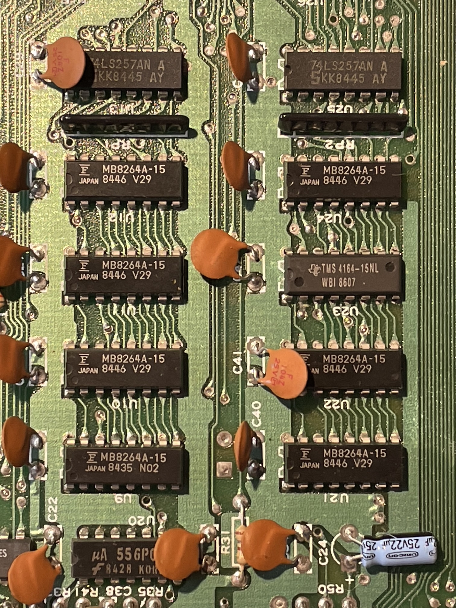
Fig. 6: a closeup of the RAM chips. They are common 1x64 kbit, one of them has been changed on my machine: there are 7 MB8264 and one TMS 4164.
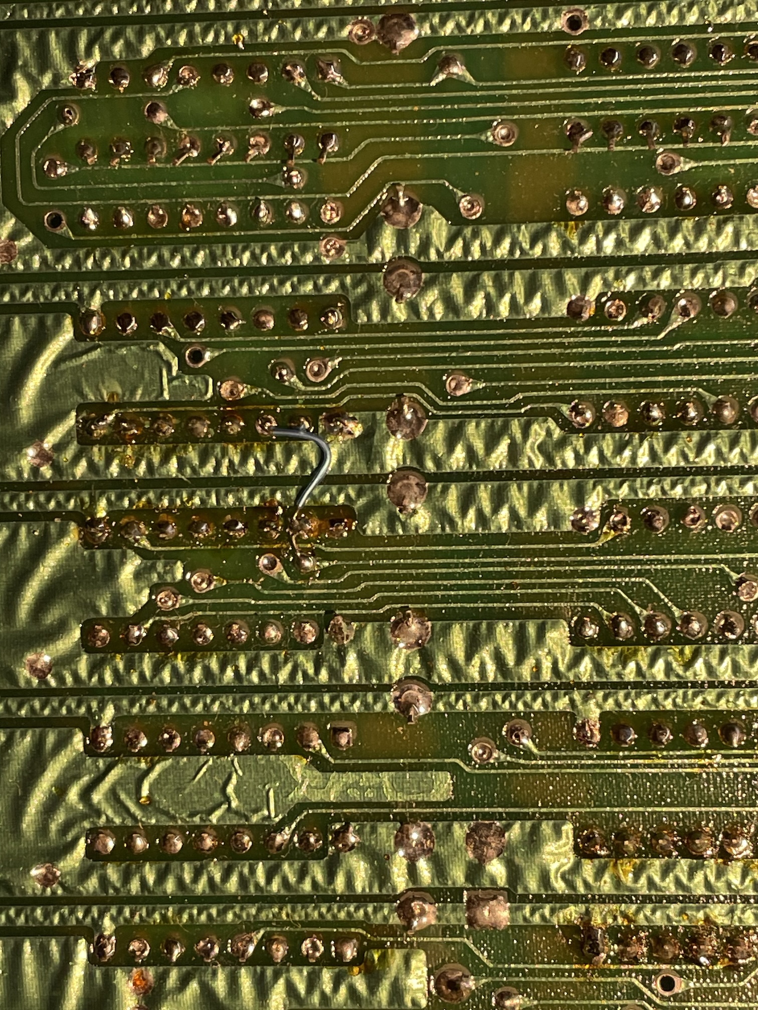
Fig. 7: Definitely, the board has been already repaired once: while desoldering U23 the technician lifted a trace and repaired it with a bodge wire. On the other hand, the wavy look of the copper track and ground plane is perfectly normal
My monitor (a Sony PVM) could lock to a PAL signal coming from the C64, so this means that clock signals are correctly generated. I checked with an oscilloscope the phi2 clock on pin 39 of the CPU (that Commodore calls MPU in the schematics). The signal was present and solid, as expected.
I also checked the /RESET signal, generated by one half of a 556 double timer circuit and present at pin 40 of the CPU. No problem on my board. Each time the computer is switched on, this signal remains low for about a second, then high. No surprises on my C64.
The TTL chips next to the RAM chips can create a black screen issue, in particular when they come in variants built by MOS. That was not the case in my C64 that sported common generic TTL chips.
Further investigation: testing the PLA
The black screen on a C64 (with video sync present) can be due to a multitude of factors. Online guides tend to orient towards a problem on U17, the PLA, which stands for Programmable Logic Array. In the very early revisions of the C64, this chip was a programmable component that was used to simplify the decoding logic and spare a number of TTL logic gates. In successive revisions, this very important function was implemented with a dedicated chip that was pin-compatible with the programmable version, but was dedicated to this sole function. However, the name PLA stuck.
It makes sense to first check the PLA on my C64. The obvious thing would be to desolder the chip and try it in a working C64. But I don't have a second machine for the tests. I was considering buying a modern low-cost replica of the PLA (they exist and work well) to do the test, but I received the first good hint from @root42: it is possible to test a C64 PLA using a TL866II-plus EPROM programmer. Since I have it, I did the test, that was successful, as visible in figures 7 and 8. By the way, I used the very nice minipro tool, that is open source and runs perfectly on the macOS terminal. I also removed the SID chip and the CIA 1, already socketed.
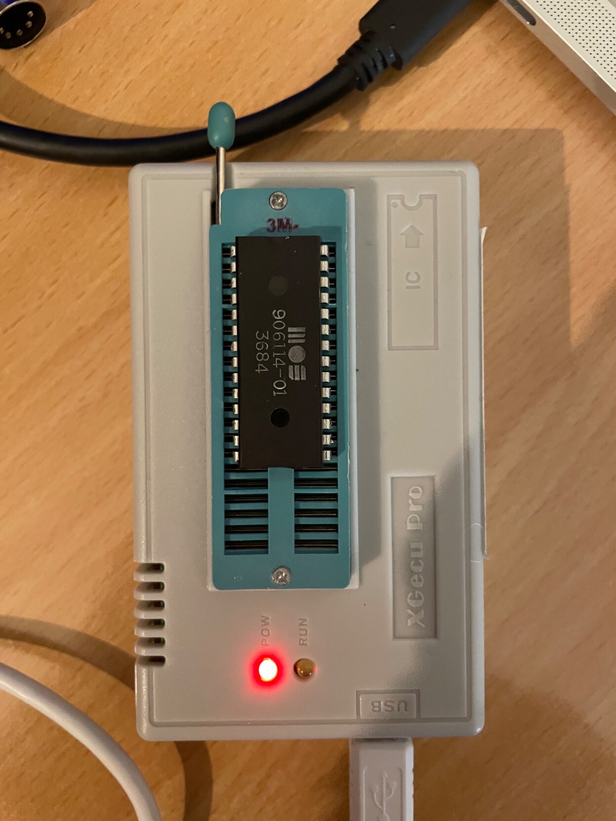
Fig. 8: The PLA of my C64 being tested on the TL866II-plus
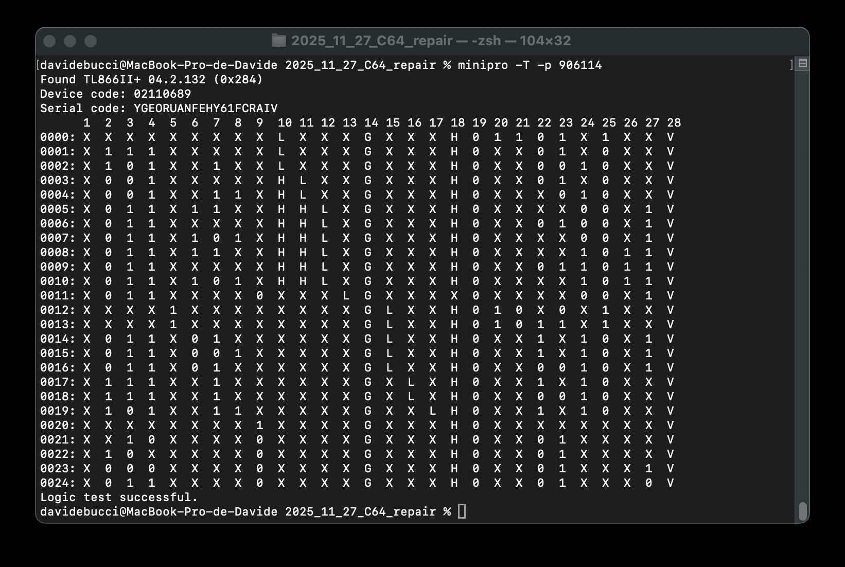
Fig. 9: The verdict: the PLA is working
The PLA seems to be ruled out! It may be possible that borderline chips would pass the test on the TL866II-plus, but I think this would not happen very often.
It is difficult to desolder chips on the C64 without lifting traces. We have already seen in figure 6 that, during a previous repair, the technician had to use a bodge wire. I used a ZD-915 desoldering gun. I have some experience with it, but not extensive. This repair was also the occasion to improve my skills. On my first desoldering attempt on the PLA, I lifted a trace under the PLA, but I was able to re-solder it on the top side, using a high-quality machined pins socket. I noticed that this kind of socket may not be the best possible choice for inserting back the original PLA, which has the pins shortened during the original install and has been desoldered. At least, it offered the opportunity to solder pins on the top side. That was the main advantage in my case.
Since the culprit of the black screen wasn't the PLA, I thought that I needed a Dead-Test cartridge to help the investigation.
Dead test cartridges
While I was asking myself which kind of diagnostic cartridge I could possibly buy, @root42 gave the suggestion to choose a switchable model that could run several ones. I ordered one that came as a kit that I assembled, and the result is visible in figure 10.
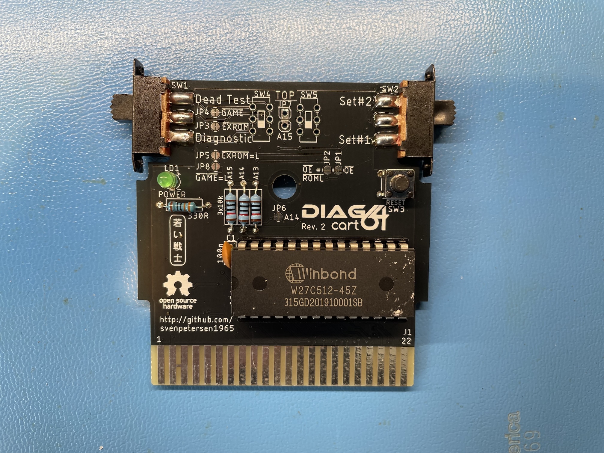
Fig. 10: The switchable test cartridge I bought as a kit. The JP7 is still missing! I realized later a jumper had to be installed there
The cartridge didn't work on the first attempt. I had a look at the most important signals on the board using my oscilloscope. Most of them looked perfectly normal, except the address line A12, which had what looked like an abnormal rise time, visible in figure 11. I wondered for a while if I had a problem with the CPU, then realized that I had mis-configured the switchable cartridge: the jumper JP7 was missing. Always read the manuals first!
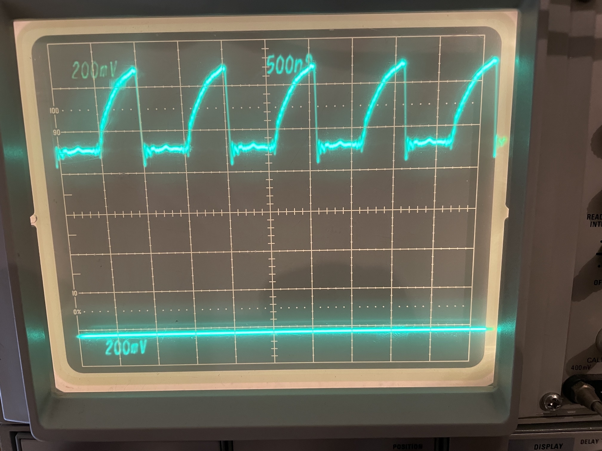
Fig. 11: The oscilloscope trace of the A12 address line, with a suspiciously large rise time. This did not look normal to me at a first glance. I was using a x10 oscilloscope probe, so the vertical scale is 2V/div.
By installing JP7, I could make the Dead-Test cartridge work. In fact, in the switchable cartridge, there are three images of EPROMs that originally were separate cartridges:
- the 781220 original Commodore Dead-Test cartridge.
- the Kick Dead-Test, an improved version of the Dead-Test cartridge
- the Commodore diagnostic cartridge, that performs a more extended test using a test harness to be connected to all interfaces of the computer.
A side note: something similar to the MAX mode does not exist on the VIC-20. Dead-Test cartridges on this computer always depend on a working KERNAL ROM to start. I saw many people trying to repair a VIC-20 forgetting this, being so used to the behavior of the Dead-Test carts on the C64.
I did not find any difference between the two Dead-Test cartridges. Both showed a single flash on the screen when the computer was powered up. On the other hand, the diagnostic cartridge only showed a black screen. A single flash on the Dead-Test indicates a fault in the RAM, on bit 0 of the data bus. On my revision of the motherboard, this points towards U21, a MB8264A-15 on my machine. I desoldered it and changed it with a TMS4164 I had as a spare, installed on a socket. I still got a single flash, so I tried with another TMS4164. At one moment, I got 6 flashes and I thought I had made some progress, but at the next attempt, I went back to the situation of a single flash. This means that there's still a problem remaining on bit 0. It was possible that all the TMS4164 in my possession were bad, but I thought it was improbable. So, I was stuck. Maybe a problem with the CPU because of that famous address line A12 that looked so strange in figure 11?
Trying out the DesTestMax cartridge
At this point, @root42 suggested me to try the DesTestMax, by Factor of Matt. I recalled to have seen it in a YouTube video by Adrian Black. It was easy to flash the DesTestMax binary on a 2764 EPROM, install it on the switchable cartridge and try the computer again. The output was a garbled screen, as visible in figure 12. It is a sort of progress, as it shows that the VIC-II was able to visualize something, at least.
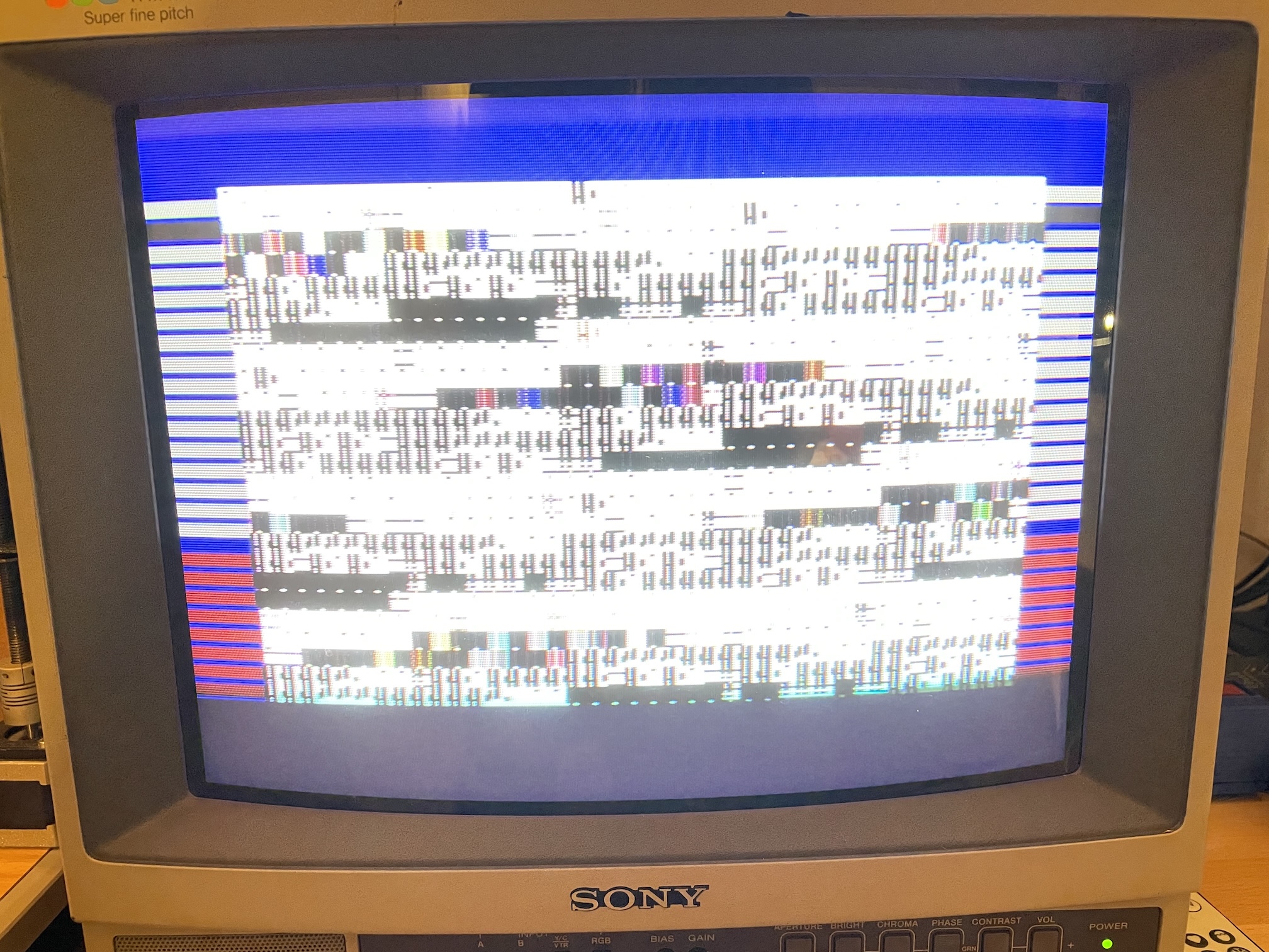
Fig. 12: The output of the DesTestMax: a scrambled screen!
The DesTestMax stores the first test screen in the EPROM. It is therefore impossible to change its contents, so that information is cleverly provided on the borders using raster interrupts. In my case, having 8 red stripes in the lowest portion of the border means that memory tests fail on all 8 bits. This is more information with respect to the original Dead-Test that only showed a single flash for the test of D0.
Having a test that fails on all the data lines suggests that there is probably an issue with memory access, rather that a single RAM chip is bad. For this reason, I tried to change the multiplexer chips 74LS257 U13 and U25. It makes sense: both the RAM and the VIC-II access the address bus in a multiplexed way. If a problem arises with the multiplexers, it is not strange that the VIC-II is not able to properly access the EPROM. Tested with my TL866II-plus, both chips were good. I had a strange situation here: I could get the scrambled screen with the original chips, but if I bought some new chips I tried to change them, I could only get a black screen. Were the new chips fake? They tested OK on the TL866II-plus, I had a look at the current on the VCC chip, and it was sensibly the same as the original chip. Definitely, they are TTL LS chips that behave like 74LS257... That was very puzzling, so I kept the original 74LS257's.
The next possible culprit could possibly be U26, the 74LS373. It allows the VIC-II chip to access to the character ROM, so if it does not work, the screen is garbled. Needless to say, it tested OK with the TL866II-plus. I did the same with U14, a 74LS258, with strictly identical results.
I thought that a possible problem was a nonworking chip on the address/data lines that could create problems. I was still very suspicious about the A12 line, which is not connected to many IC's and still showed the slow rise time visible in figure 11. I desoldered the CIA 2, as well as the BASIC and character generator ROMs. While doing tests, I checked the signal on the PLA and I noticed that on pin 20 the signal A4/A12 looked suspicious. So I lifted the pin and tried to connect it to 5V via a resistor (just in case). The screen changed and looked less garbled, as shown in figure 13. I thought it was a consequence of the bad behaviour on the A12 line. I also noticed I could get a slightly less mangled screen by applying a 1 kΩ pull-up resistor to the /VA14 line, on pin 2 of U2, the CIA2. There was also the possibility of a problem on the PLA that was not fully detected by the previous test with the TL866II-plus.
To summarize, at this moment, I was becoming more and more suspicious of the CPU because of the A12 line, and I wasn't fully sure about the PLA.
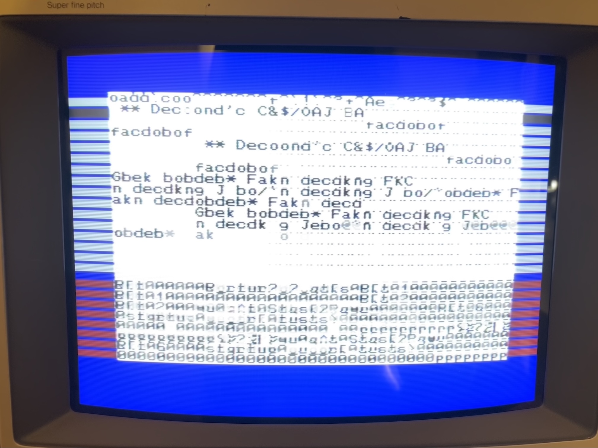
Fig. 13: A slightly less scrambled screen from the DesTestMax
A useful hint in a Jan Beta YouTube video: A12 is normal!
I have some health issues in this moment. Nothing serious, but they don't allow me to stay sitting at my bench for a very long time. As a result, I have time to think, document myself and watch other people repairing C64 boards. Most of the time, faulty chips are found by comparing them with a working C64, that I don't have. I could, however, stumble on a very nice video by Jan Beta, who tried to repair a very stubborn C64 ASSY NO. 250425 like mine. He noticed the strange behaviour on A12, suspected the CPU as I did and finally compared it with a working machine. He could conclude that the slow rise time is a perfectly normal condition! Watch Video 1 if you like this kind of things (if you have read this article until this point, it is probably the case) and like and subscribe as Jan has a wonderful channel. Look at Jan's oscillogram at 15h15 and compare it with figure 11 of this article. Discussing with Jan, he pointed out this useful post by Sven Petersen confirming there are "Lots of wonky looking signals on a working C64. :D ".
Video 1: A very interesting repair of a stubborn C64 by Jan Beta. At 15:14, he notices that the A12 line is strange, but then realizes it is a perfectly normal condition at 26:37 by comparing it to a working machine
Knowing that in my case the CPU was most probably OK, I was still thinking about a problem with the PLA. However, at that moment, I had tested most of the essential chips of the computer and another idea popped up: what if there's a problem on the board? I tested for continuity all the pins of the sockets I installed for the TTL chips, the RAM, the PLA and the VIC-II, and they were good. Was a short-circuit possible somewhere? I started on the data and address bus on the processor. Then, I tried on the multiplexed address lines and... what the heck is that 33 Ω resistance between 13 and 11 of the 4164 RAM chips? Sure enough, the problem was a short-circuit between pins 2 and 3 of the resistance network, composed of 33 Ω resistors. Remember that problem on the A4/A12 line? Remember the different results with two different 74TL257? It makes sense that strange behavior would occur with such a short-circuit! Clearing the short yielded a much better result with the DesTestMax cartridge. The initial tests are passed, and the screen memory is the EPROM is displayed correctly. However, when the cartridge starts using the RAM as video memory (much more practical if you want to write things), the screen looks scrambled as visible in figure 14.
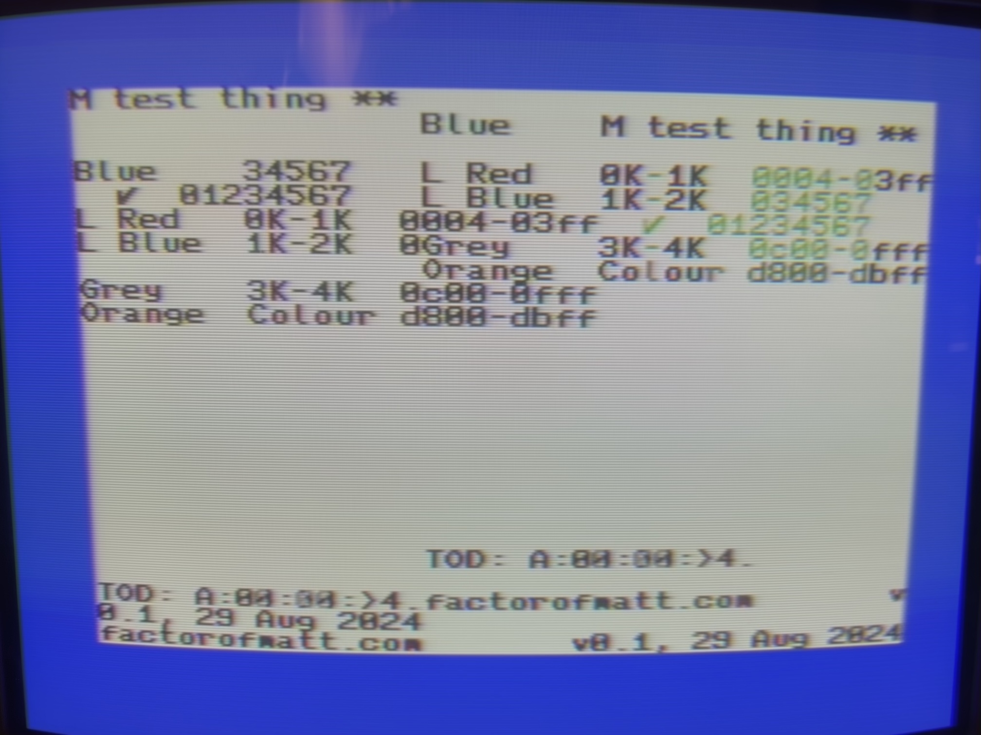
Fig. 14: clearing the short on the resistive network RP1 yields a much better, but still scrambled DesTestMax screen
The problem here was a false contact on U14. The original 74LS258 chip has very short legs and the machined pins header I employed does not work well with IC pins that are not in good condition. Pushing the 74LS258 on the socket yielded a RAM test that was passed with flying colors, as visible in figure 15! Of course, the CIA's were not installed, so the counters on the DesTestMax could not be updated. The results were also good with the Dead-Test, this time (figure 16).
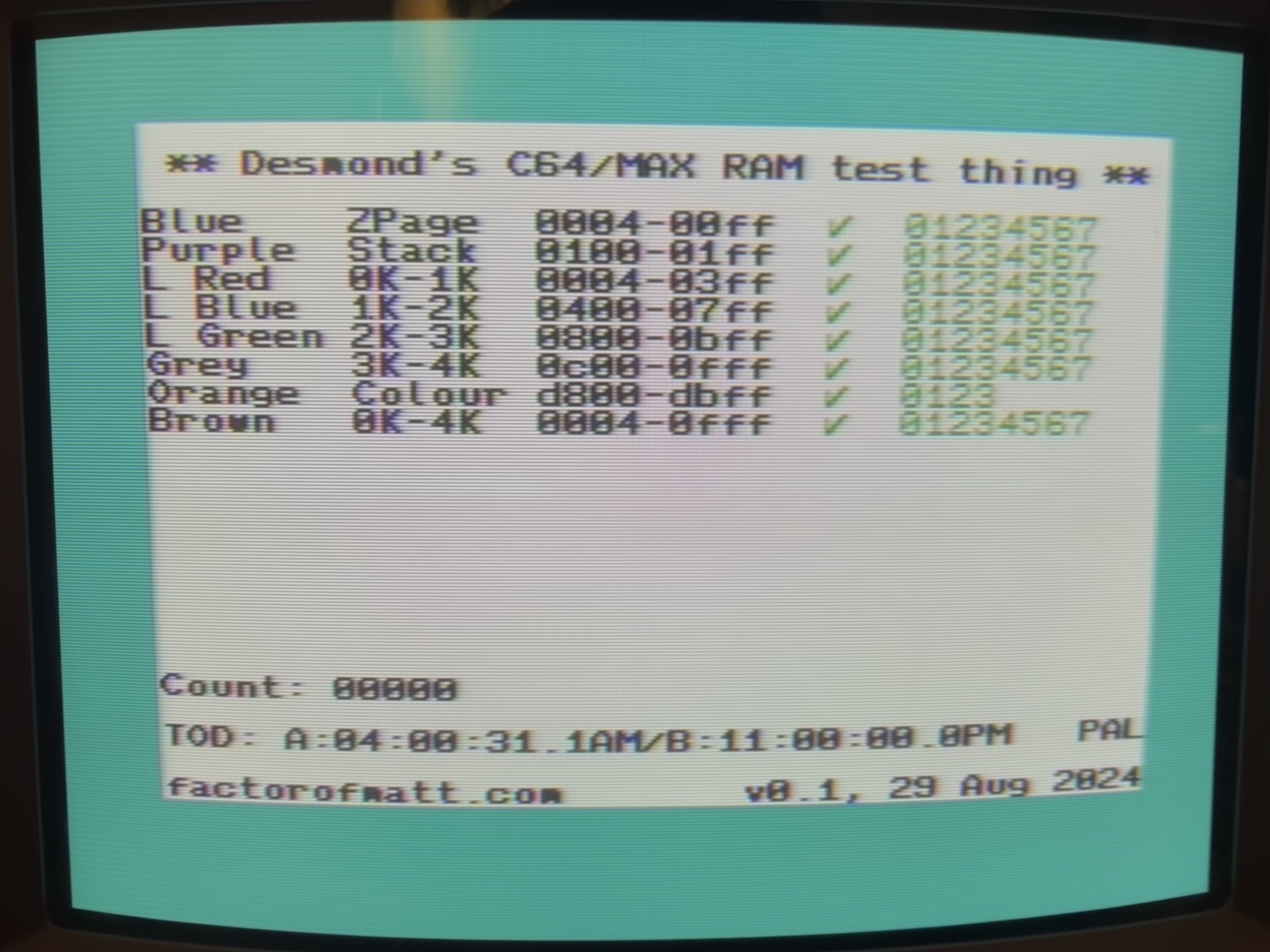
Fig. 15: memory tests on the DesTestMax passed with flying colors!
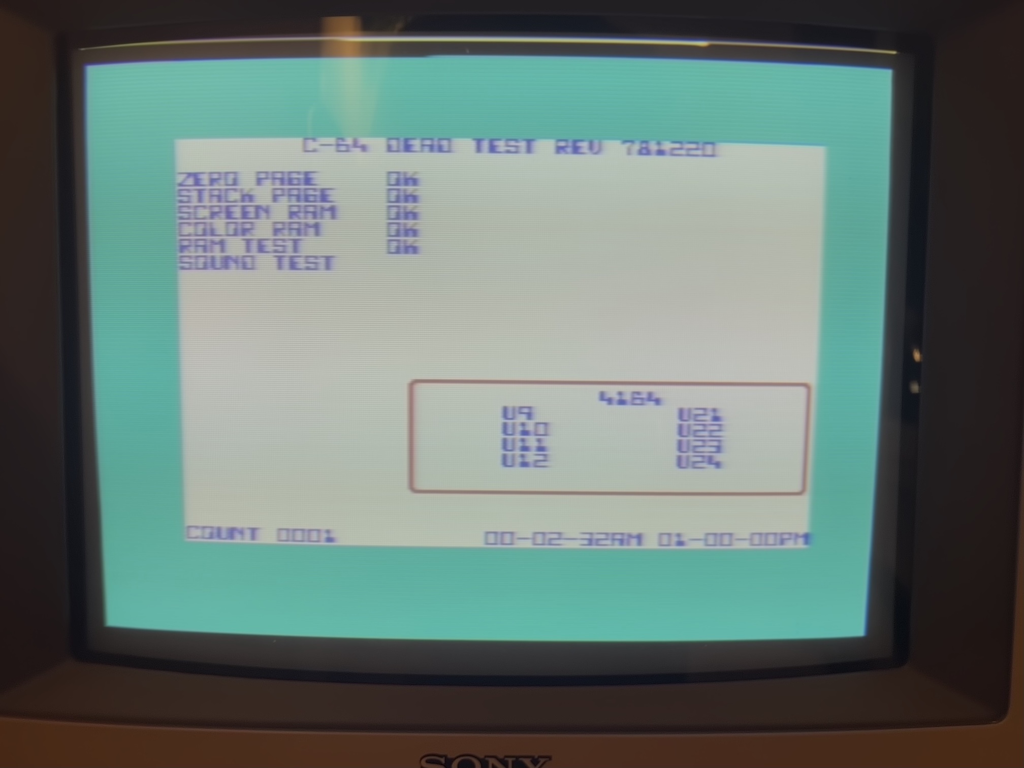
Fig. 16: no problem are spotted by the Dead-Test, either (apart an absent CIA).
The blue screen of life
Having passed the tests of the DesTestMax and the Dead-Test cartridge that operates in the Ultimax mode encourages us to try to get a blue screen of life, i.e. the C64 prompt. For this, we need the ROMs. I thought for a few minutes that the KERNAL rom was broken as the computer still displayed a black screen at startup. When I tried to read it on the TL866II-plus (you have to configure it for a 2364A EPROM), I got results that looked strange until I realized that I did a confusion between the KERNAL (2364A) and the character generator ROM (2332A). When I placed all the chips at the right place, I could obtain the classic C64 prompt for the first time (figure 17): SUCCESS!
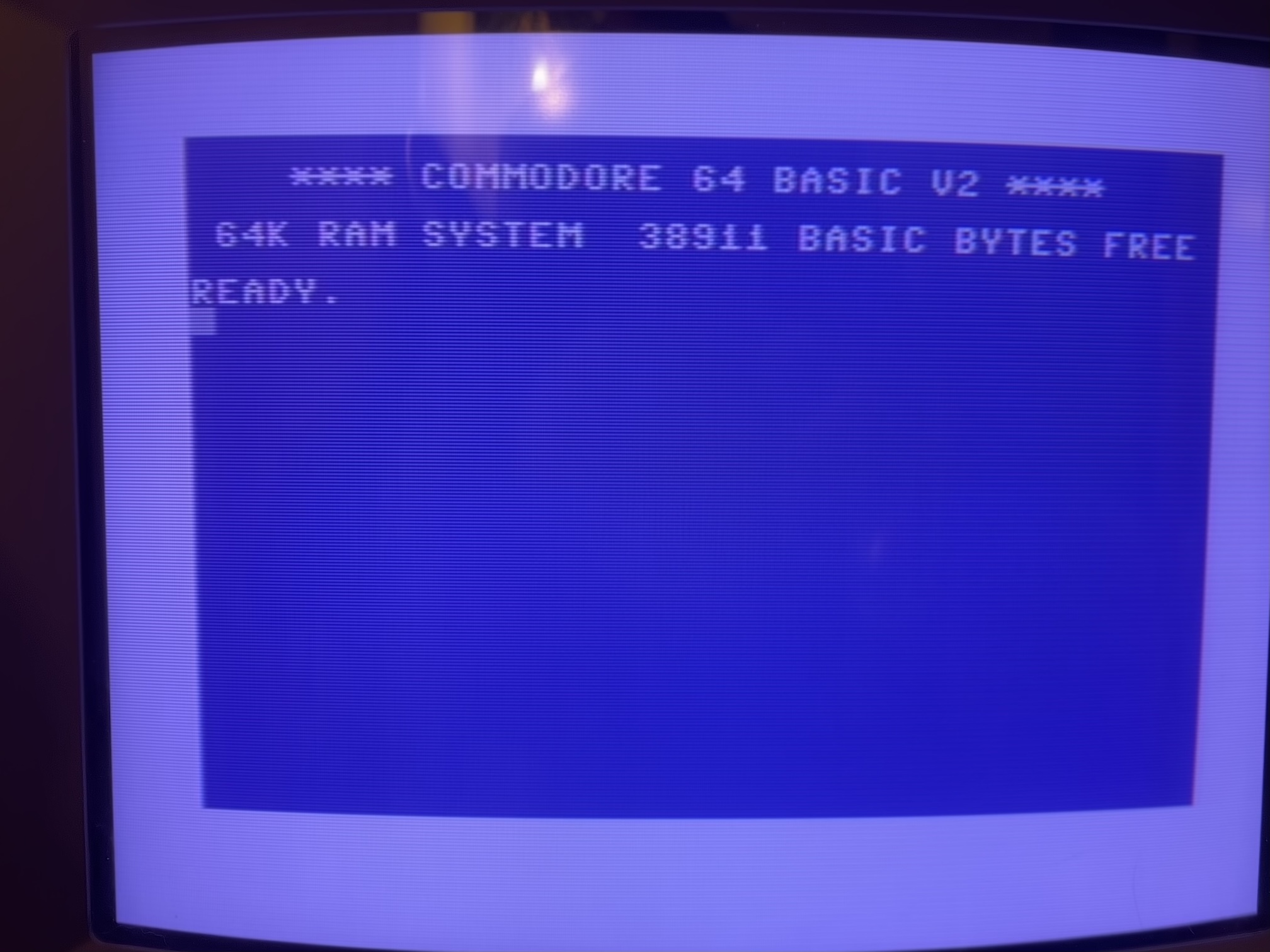
Fig. 17: the well-known C64 prompt, nicknamed "blue screen of life"
I put back the original SID and it was OK. Further testing of the machine revealed a problem: the serial interface was not working. I quickly found I had forgotten to repair a lifted trace on the CIA2. I had to add a second bodge wire to this board. Fair enough! A second problem was general instability and random reset that indicated a false contact somewhere. I solved it by using a new 74LS258 for U14 with longer pins than the original.
Where did this short come from? It may be possible that I created it when I desoldered U13 and U21 that are very close to the RP1. On the other hand, all the components proved to work correctly when I put them back in the working machine. It may be possible that the machine wasn't working for another reason, such as false contacts or a bad solder joint. Maybe I introduced the short and repaired a false contact. But the simplest option is that the short (quite small and barely visible) was already there when I received the computer. Maybe the previous repair never went well, after all, and this C64 remained unused and broken for many years.
Repairing the C64 keyboard
Once tested that everything was working on the electronics of the C64, it was time to solve the problem with the broken key. The computer received a shock (a small mark on the plastic is visible above the "1" key in figure 2) that probably broke the plunger of the arrow key. Opening the keyboard mechanism is not difficult, one only has to remove all the small self-tapping screws that keep the PCB together with the plastic frame of the keyboard that supports the plungers. You only need a little patience, as visible in figures 18 and 19.
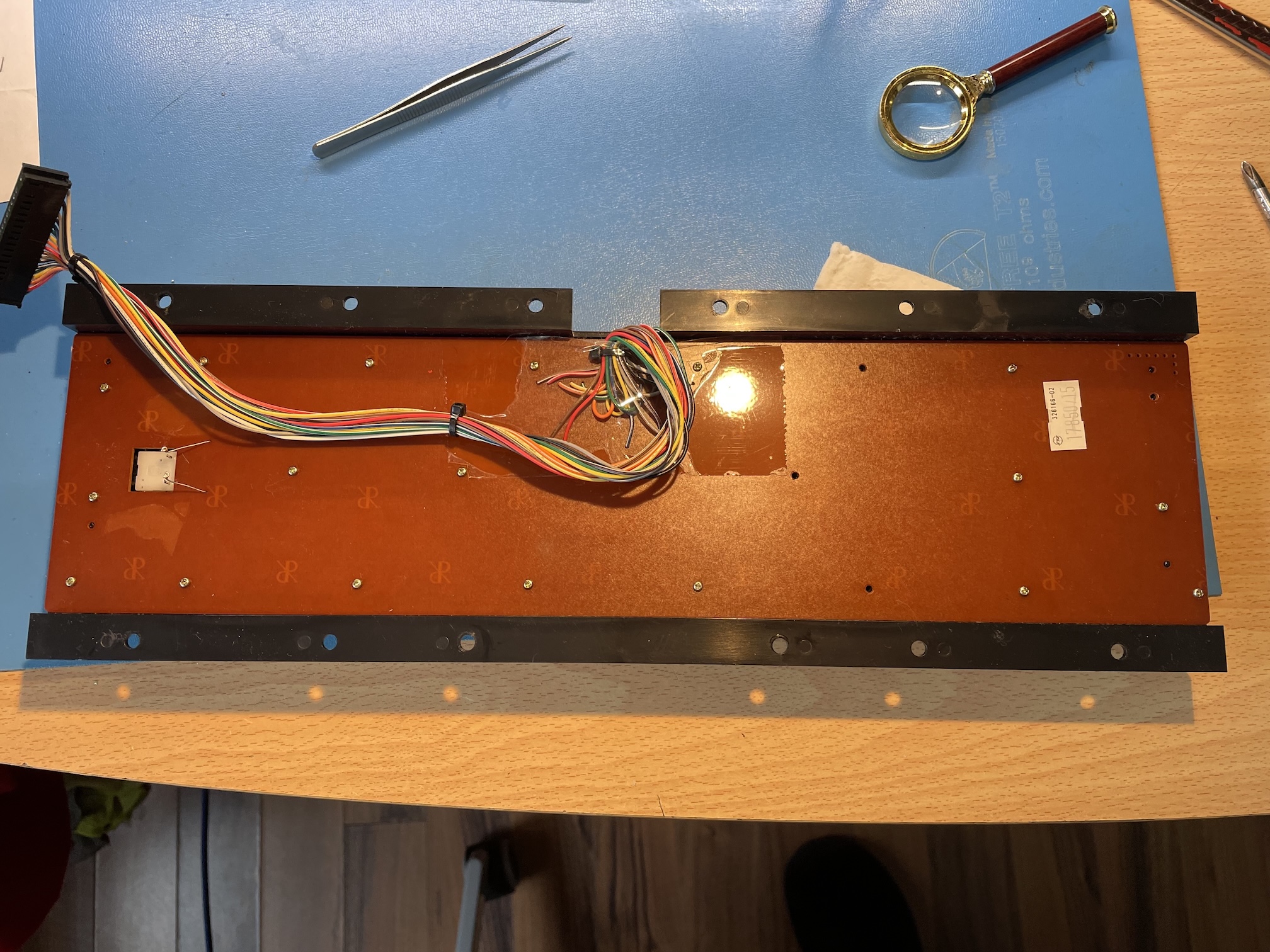
Fig. 18: the back of the C64 keyboard, built by Mitsumi
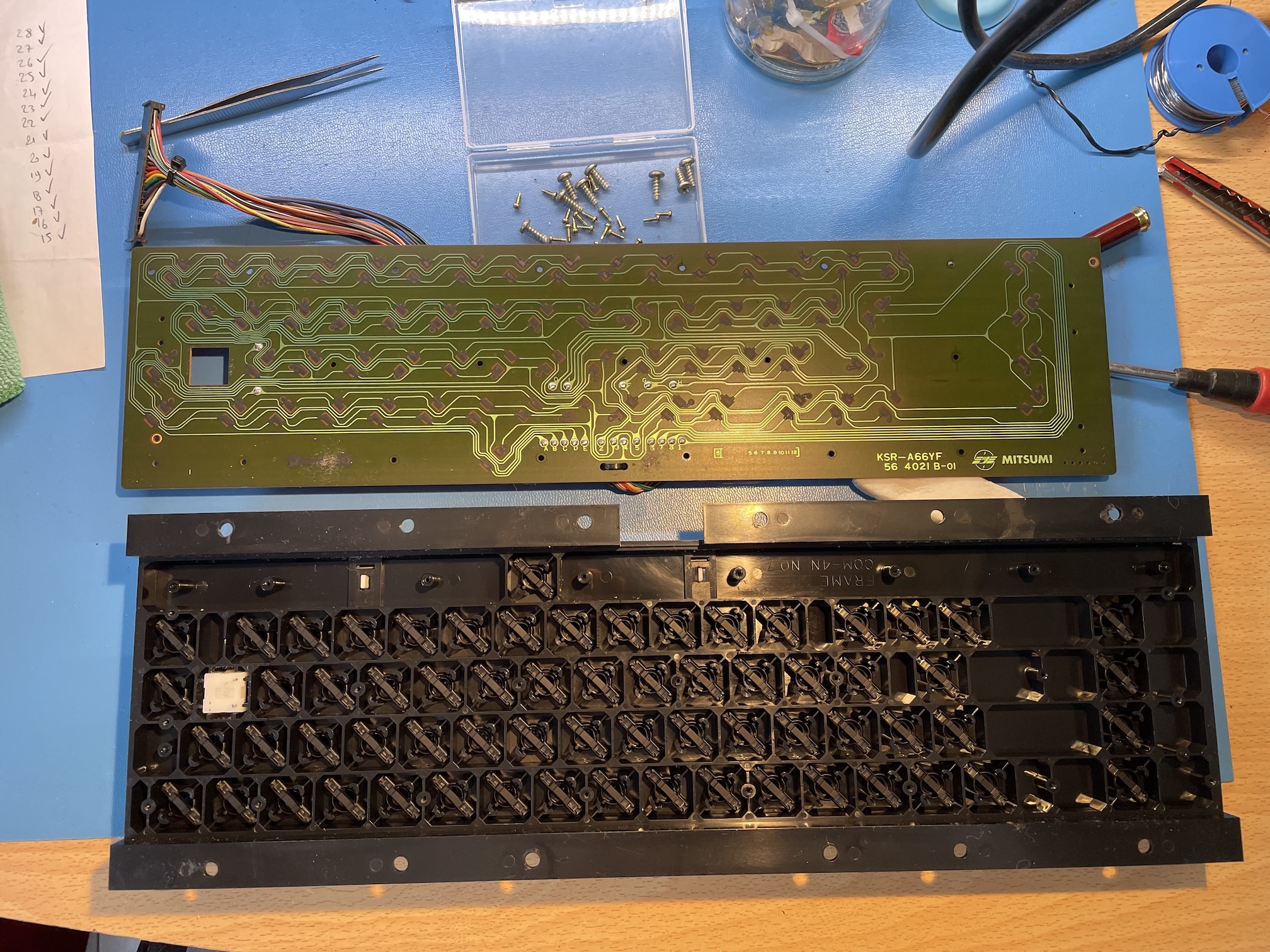
Fig. 19: the keyboard, open. Notice the graphite-coated contacts. This is slightly different from the keyboard of my VIC-20 where the contacts are gold-plated
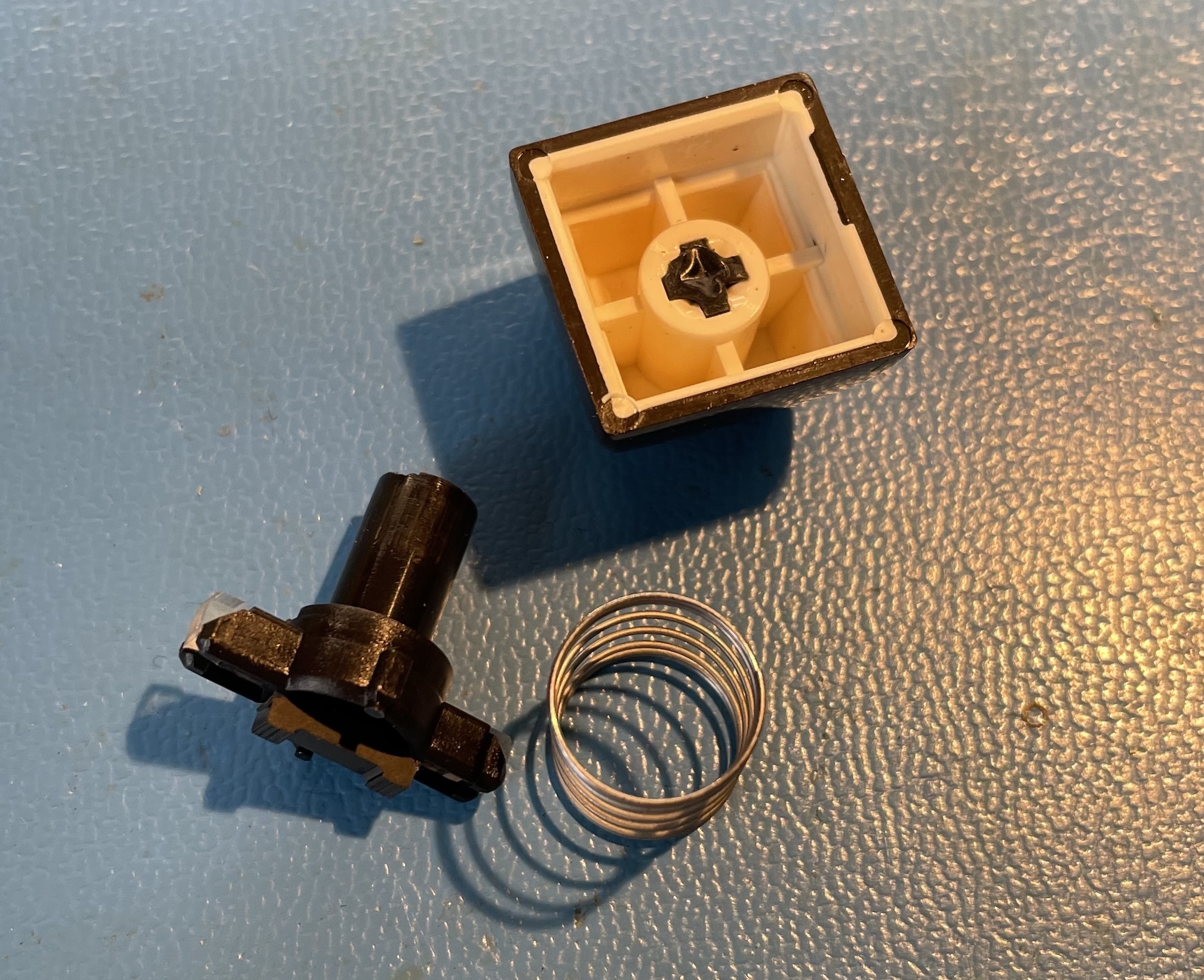
Fig. 20: the keycap, with the spring and the broken plunger
Fortunately, the key cap and the spring were part of the auction. I could already successfully repair a similar problem on my VIC-20 in 2024, so I just had to 3D-print another plunger. The only difference is that my 3D printer works better now than in 2024 and the printed plunger was more precise.
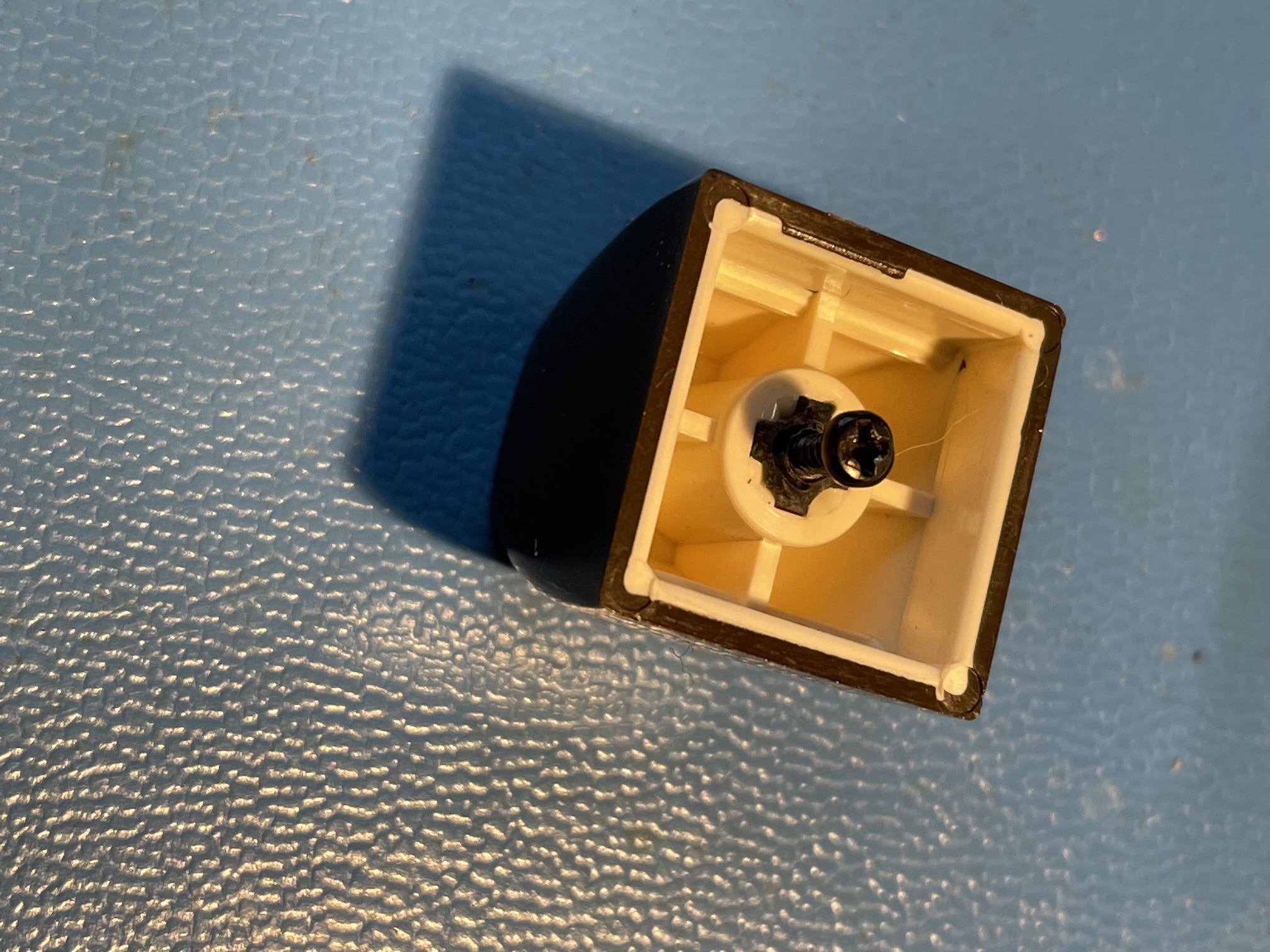
Fig. 21: a trick to extract the broken part of the plunger from the keycap
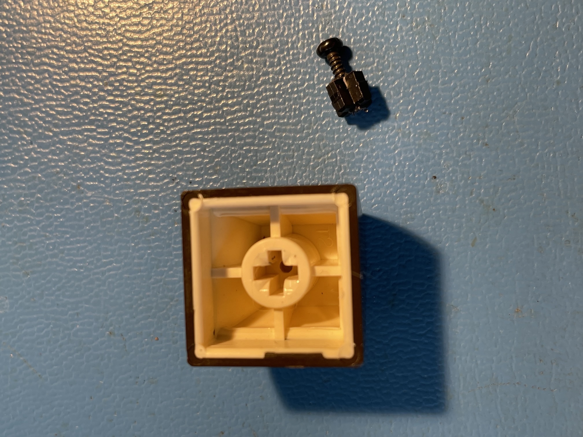
Fig. 22: The broken part of the plunger is easily removed pulling on the screw
It may be tricky to remove the broken part of the plunger from inside the keycap. A technique is to drill a 1mm hole in the center of what remains of the plunger and then use a self-tapping screw (figure 21). With a small pair of pliers, the screw can be pulled, removing the broken plunger without difficulty (figure 22).
The plunger is a perfect part for 3D printing: it is small, it has a complex shape but it does not require an outstanding tolerance, it must be functional, but it is not visible when the computer is assembled. The result (printed in about 10 minutes) is represented in figure 23. Putting the keyboard together is not difficult: it's barely the inverse of disassembly. One just has to pay attention not to lose one of the smal self-tapping screws.
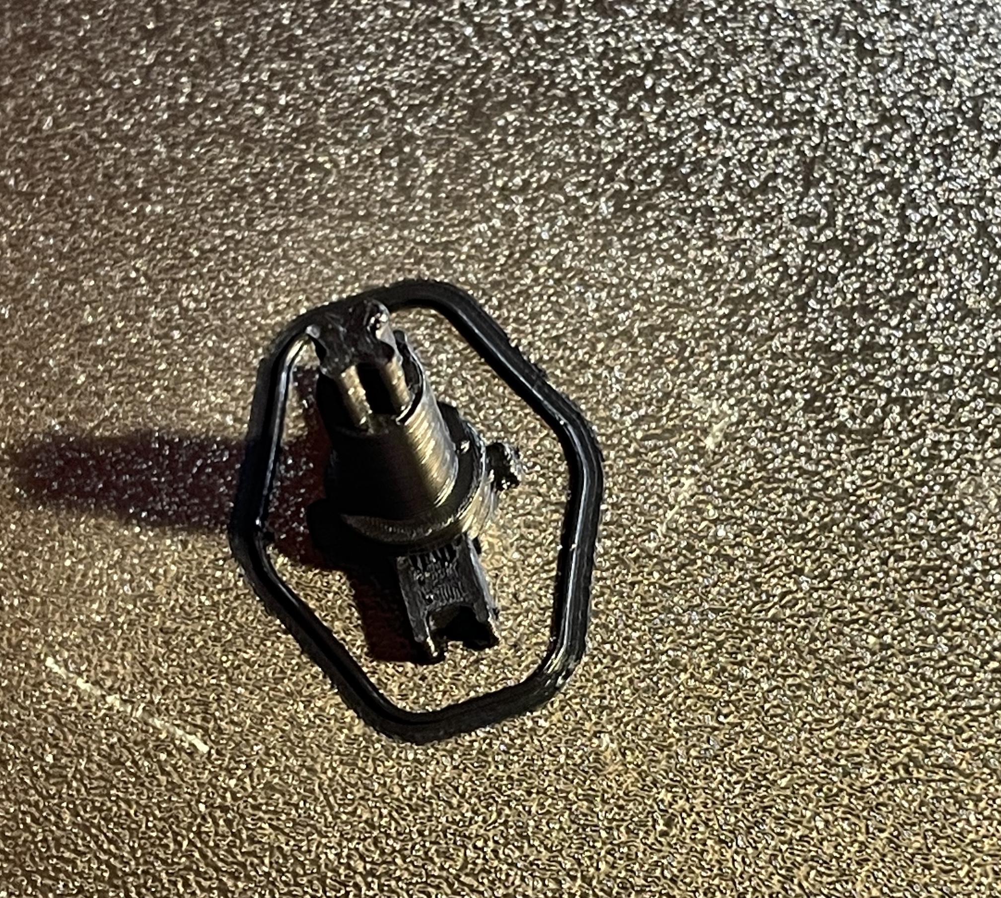
Fig. 23: The 3D printed plunger immediately after finished printing
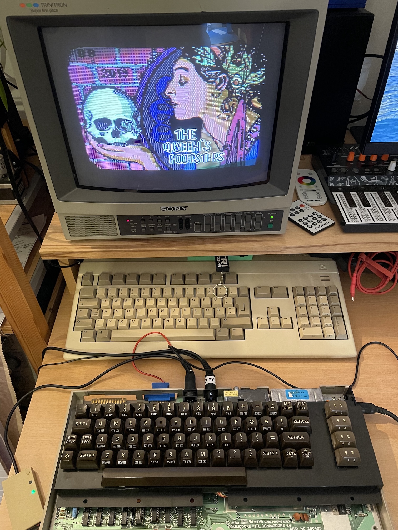
Fig. 24: A functional test: playing to The Queen's Footsteps loaded by IEC2SD
Testing the keyboard requires typing. What's better than a text adventure like The Queen's Footsteps? Figure 23 shows the loading screen of this award-winning game :-)
I found the 3D model of the key plunger on Thingiverse. Now the repair is complete, and the rest is only cosmetics. Of course, I cleaned with a glass cleaner and soft cloth the whole case of the computer, lightly scrubbing with a magic eraser to clean a few black marks. The computer was in good shape overall, so the end result is very pleasing.
Conclusion
Repairing this C64 has been a pleasant journey, overall. I had fun investigating the faults, I was able to improve my desoldering skills and had pleasant interactions with many enthusiasts on Mastodon and in particular with @root42 and Jan Beta. The TL866II-plus also proved to be very valuable for troubleshooting, thanks to the possibility of bench testing logic integrated circuits. I also learnt some useful lessons:
- Hot air is your friend while desoldering, even if you have a (cheap) desoldering gun.
- Dead-Test can guide you in a direction, but the results have to be interpreted.
- Always double-check the board, especially if it has already been repaired.
- Machined pin sockets are perfect for new integrated circuits, but do not tolerate well inserted pins in bad conditions.
It took a while as I did a pause for some vacations and because of my current health condition, but it was a fun and rewarding experience. I'm really happy about it and I am also happy that it wasn't a elementary fix. It took longer, but I have learned more in the process! I would like to thank again @root42 and Jan Beta for their patience and their hints that guided me towards the correct direction.
What remains to be done now is use the computer in the next few months to see if other problems arise. It will not be difficult! I will update this page for new adventures.
Log
- January 24, 2026 - First version of this page. Corrected a typo. .
License

This work is licensed under a CC BY, NC 4.0 licence.