CPU and TED temperatures in a Commodore Plus/4
Is temperature a big deal? Spoiler: Nope.
Introduction
I recently acquired a Plus/4 with a broken keyboard. I never saw one of them in person before, but a childhood friend of mine used to have its smaller sibling, the Commodore 16. Reading here and there, one of the first things that pops up almost immediately is the presumed lack of reliability of the MOS 7360 TED and the MOS 8501 CPU chips. Many theories are proposed and, in particular, many claim that the biggest issue with those chips is related to heat [1]. When I wrote on my Twitter account that I had a (almost) working Plus/4 in my hands, I have been immediately suggested to put a heatsink on those chips on my computer. All the relevant chips of the machine were produced in the very last weeks of 1984. I had some heatsinks and I was planning to use them.
However, while I was repairing the keyboard, I had to test the computer for a certain time to see if I was able to clean all the keys. I tried to touch the 8501 CPU to see if it was running hot. As i did for the ZX Spectrum's ULA, I use an old and simple rule of thumb: if you can't stand your finger on top of a chip because it is too hot, then it may deserve a heatsink. To my surprise, I noticed that the Plus/4 CPU was barely warm, contrasting with all the Internet wisdom I read, suggesting temperature was a big deal there! I thus decided to investigate.
This article reports some measurements, done with a small Pt100 temperature probe, as well as excerpts from a discussion I had with Bil Herd, the hardware engineer in charge of the development of the Plus/4 computer.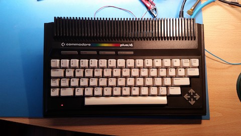
Fig. 1: The Plus/4 on my bench. What a beautiful machine!
Reliability and temperatures
My experience seemed in contrast with many advices I read on technical forums. When in doubt, ask an expert. I therefore decided to write to Bil Herd, the engineer who was in charge of the Plus/4 design. Bil runs c128.com, a very nice website with a forum and he enjoys talking about his experience at Commodore. I got a kind answer from him that I could include in a post on the C128 forum. Here is an extract from what Bil wrote to me. I cut out a few sentences that you can find the C128 post [2]:
"There are a couple of realities regarding heat and the chips of the TED series (264/Plus4/C16/ etc). The reality is that we made consumer devices that were meant to last about 3-5 years after which we would not have cared about the remaining lifetime left.
[...]Then there is the effect of heat on chips, put bluntly if heat was a problem the chips would have died their first year. The chips that are left after 35 years are proof that heat isn't an issue. Yes I am aware that people take off the RF shield (which invalidates FCC, we had no choice) and put a heatsink n but in still air (or no convective chimney) I would submit they might actually run hotter, I have plans to test this BTW.
The REAL thing that breaks a 35 year old chip some of the time, (sometimes they just break, like your old favorite glass that chips one day) is the thermal cycle of applying power. Think of when a light bulb blows, it's when it's cold and there is a thermal shock, that creates a true physical stress on the die.
Heh, maybe the answer is we should pre-heat the chips before turning them on. >:) Think about this, it's counter intuitive unless you think about the actual failure mechanism.
The worst I am seeing right now are some people posting their theories that the chips should have been designed to run even cooler and more money spent and one person in particular has called everyone involved in the design/production processes incompetent to include process engineers, chip designers, mechanical designers, hardware engineers and purchasing agents, meanwhile they have never actually been exposed to production, design or real life physics on any level, and they simply don't listen when we explain how things really work from having been there and with experience making millions of these things."
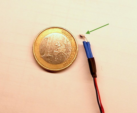
Fig. 2: Arrow indicates the tiny Pt100 temperature probe I used with a Philips PM2521 multimeter
We live wonderful times. If someone would have said to my 7-year old self that 33 years later I could discuss with the actual guy who designed the C16, Plus/4 and my beloved C128, I would have never believed that.
After reading Bil's answer, I thought that it would have been interesting to measure temperatures on the CPU putting the PCB inside and outside the case, to have some real data. A few months ago, I bought some small Pt100 probes [3] that I wanted to use with my vintage Philips PM2521 multimeter that has an appropriate input for them. As visible in figure 2, they are quite small: I attached one of them to four small wires (the PM2521 uses a Thompson bridge with 4-wire connection to the probe) and used it to measure some data, summarised in Table 1, where Delta t indicates the increase from ambient temperature. I could put a tiny quantity of thermal compound on the probe, so that the thermal contact with the CPU was improved. However, temperatures varied a little bit when moving the probe, increasing the measurement uncertainty. I think it safe to admit that all temperatures I measured were affected by a +/-2°C uncertainty, except for ambient temperature where I did not have any problem of thermal contact and errors are those of the sensor and the multimeter alone (in the +/-1°C ballpark). In such a limited temperature range, the sensor and multimeter error are canceled out in the Delta t calculation and I would expect the uncertainty in this column is +/-2°C.
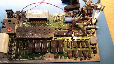
Fig. 3: Measuring CPU temperatures on the Plus/4 CPU, with the bare board on top of my bench. No video nor peripherals were connected.
| Parameter | Condition | Measurement | Delta t |
|---|---|---|---|
| Ambient temperature | Open air | 22.6°C | - |
| Centre of CPU | PCB on the bench, after 45 min | 40.7°C | 18.1°C |
| Edge of CPU | PCB on the bench, after 10 min (*) | 32°C | 9.4°C |
| Centre of CPU | PCB in case, after 45 min | 52.5°C | 29.9°C |
| Edge of CPU | PCB in case, after 10 min (*) | 37.7°C | 15.1°C |
| Edge of CPU | PCB in case, after 10 min (*), heatsink | 37.5°C | 14.9°C |
| Centre of heatsink | PCB in case, after 10 min (*), heatsink | 47.8°C | 25.2°C |
Table 1: Temperature measurements for the CPU. Uncertainty on data is +/- 2°C. Asterisk (*) means that I switched off the computer, took a few minutes to move the probe and prepare the measurement, then switched the computer on again and waited 10 minutes.
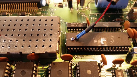
Fig. 4: Measuring temperature on the edge of the CPU package
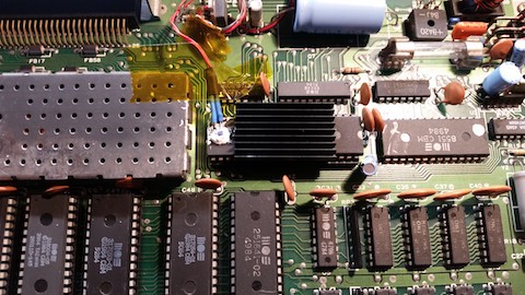
Fig. 5: Measuring temperature on the edge of the CPU package with the heatsink installed
I wanted to test the effect of a heatsink on the CPU and, since it is impossible for me to measure temperatures in the centre of the chip when the heatsink is in place, I decided to measure the temperature also in another place of the CPU, that would remain accessible even when the heatsink was installed, so that I could compare its effect. Figure 4 shows what it means "Edge of the CPU" in table 1.
Without the heatsink, temperatures were perfectly normal from what I expect from a well-behaved electronic circuit. An increase of 30°C over the ambient temperature is normal and perfectly tolerable for a consumer product expected to last 3-5 years, as Bil wrote (and even much more of that).
Since I was curious about the effect of a heatsink, I put one on the CPU with a little bit of thermal compound and two small drops of cyanoacrilate glue. Temperature on the edge of the CPU remained constant (see figure 5). I could not measure the temperature of the centre of the CPU anymore as the heatsink is on the way, it is plausible to think that it remained a few degrees cooler. I could place the sensor inside of the fins of the heatsink at the centre and temperature was about 5 degrees colder than the CPU centre, without the heatsink.
As the CPU runs relatively cool, I tried to measure temperatures for the TED chip, by putting the probe between the copper finger that is attached to the RF shield and the chip itself. I put some thermal grease: this is not an optimal situation for the thermal contact between the finger and the chip, as the probe has a certain thickness. See figure 6. Results are shown in table 2. The TED chip runs even cooler than the CPU itself, even if the correct placement of the probe could not be verified when the RF shield is on.
| Parameter | Condition | Measurement | Delta t |
|---|---|---|---|
| Ambient temperature | Open air | 22.2°C | - |
| Centre of TED chip | PCB in case, after 45 min, RF shield on | 44.3°C | 22.1°C |
Table 2: Temperature measurements for the TED chip. Uncertainty on data is +/- 2°C.
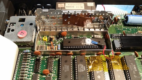
Fig. 6: Position of the Pt100 probe on the TED chip, before closing the RF shield
Conclusion
The goal of this article was to measure the temperature for the MOS 8501 CPU in different situations to see if it was excessive. A stock Plus/4 was employed, placing a small Pt100 probe on the CPU, with the TED chip under the RF shield enclosure. Results for the CPU showed an increase of 29.9°C +/-2°C with respect to the ambient temperature, perfectly normal in a consumer product of the era. Adding a small heatsink decreased slightly the CPU temperature increase to 25.2°C +/- 2°C.
Temperature of the TED chip was measured too, and an increase of 22.1°C was found, by placing the Pt100 probe between the TED chip and the copper finger of the RF shield.
In conclusion, I think that the overall reliability of the CPU and the TED chips is virtually unaffected by the presence (or absence) of the heatsink. If 8501 CPU's and TED's tend to break (but after 35 years this may not be unexpected even from chips considered to be very reliable), it is not because of their working temperature.
Addendum
It seemed that this article has sparkled a certain interest and a controversy followed almost immediately (see for example [4] that reports a really interesting discussion). Just to clarify my position:
- I am not saying here that Plus/4 are perfectly reliable, just that their presumed unreliability does not seem to come from a temperature issue.
- The presence of hot spots in the CPU die is certainly possible. Packages try to spread heat as much as possible. This can be done in a dual in line package by means of the lead frame and, optionally, with a heat spreader, positioned very close under the lead frame. A heatsink on the top of the case may reduce overall temperature (only if there is enough air circulating around it), but (unfortunately) it is probably much too far from the die to improve the situation when hot spots are present.
- If a poor reliability comes from the adoption of a new technological process that is then gradually improved (apparently the 8501 CPU and the TED chip were produced with HMOS 2 process which was new at MOS), one may expect that the first produced chips are less reliable than the last ones. This may explain alone the improved reliability of the repairs employing chips more recent than the originals, with the heatsink not playing virtually any role.
- Classic computers are like classic cars. They break. Repairing them is just part of the experience. When possible, a collective effort must be done to source parts and find solutions employing things such as FPGA's or modern components for chips that become unfortunately rare to find.
Linkography
[1] - "There are 3 main reasons for a dead 264 system - CPU (7501 or 8501), TED (7360 or 8360) and PLA (251641-02). All three are prone to overheating." (February 10, 2019)
http://www.retroisle.com/commodore/c16plus4/techdetail.php
[2] - Discussing with Bil Herd http://c128.com/plus4-cpu-and-ted-temperatures-and-heatsinks
[3] - NB-PTCO-160, Farnell 2748869
[4] - https://plus4world.powweb.com/forum/37711
Log
February 19, 2019: Italian translation and corrections here and there
February 14, 2019: Written the "Addendum"
February 11, 2019: Added measurements of TED temperature
February 10, 2019: First version of the page, with CPU temperatures
License

This work is licensed under a CC BY, NC 4.0 licence.
