
Refurbishing an HP4952A protocol analyzer
Fixing the keyboard and tearing all apart
Reaching the "pyro-capacitor"
Other interesting things about the HP4952A"
Conclusion
Introduction
A few days ago, I refurbished an HP4952A serial communication analyser. I posted some pictures of the process on Twitter and they gathered some interest. I thought it would be useful to put together this page on my blog, as any Twitter content older than 20 minutes becomes basically forgotten.
Many years ago, I could save an HP4952A from being scrapped. To find information about HP gear, as usual, a good place where to start is the HP Museum [1]. This machine is a protocol analyser, able to connect to a large variety of RS232 systems implementing many different protocols (asynchronous and synchronous, BSC, SDLC, X.25, X.21 and SNA).
It remained for years in my basement, but a few days ago I decided to took it out again. As visible in figure 1, it was very crusty, two soft keys didn't work anymore and a "pyrotechnic capacitor" just blew in the power supply, a few minutes after I switched it on, releasing a puff of smelling smoke. This poor little thing desperately needed some good TLC! The HP4952A has to be connected to an external pod and I had the very dirty HP18179A interface shown in figure 2. All in all, the HP4052A is a undeniably cute instrument: the keyboard is small but enjoyable and the CRT screen (albeit very dirty in my case) was very sharp.
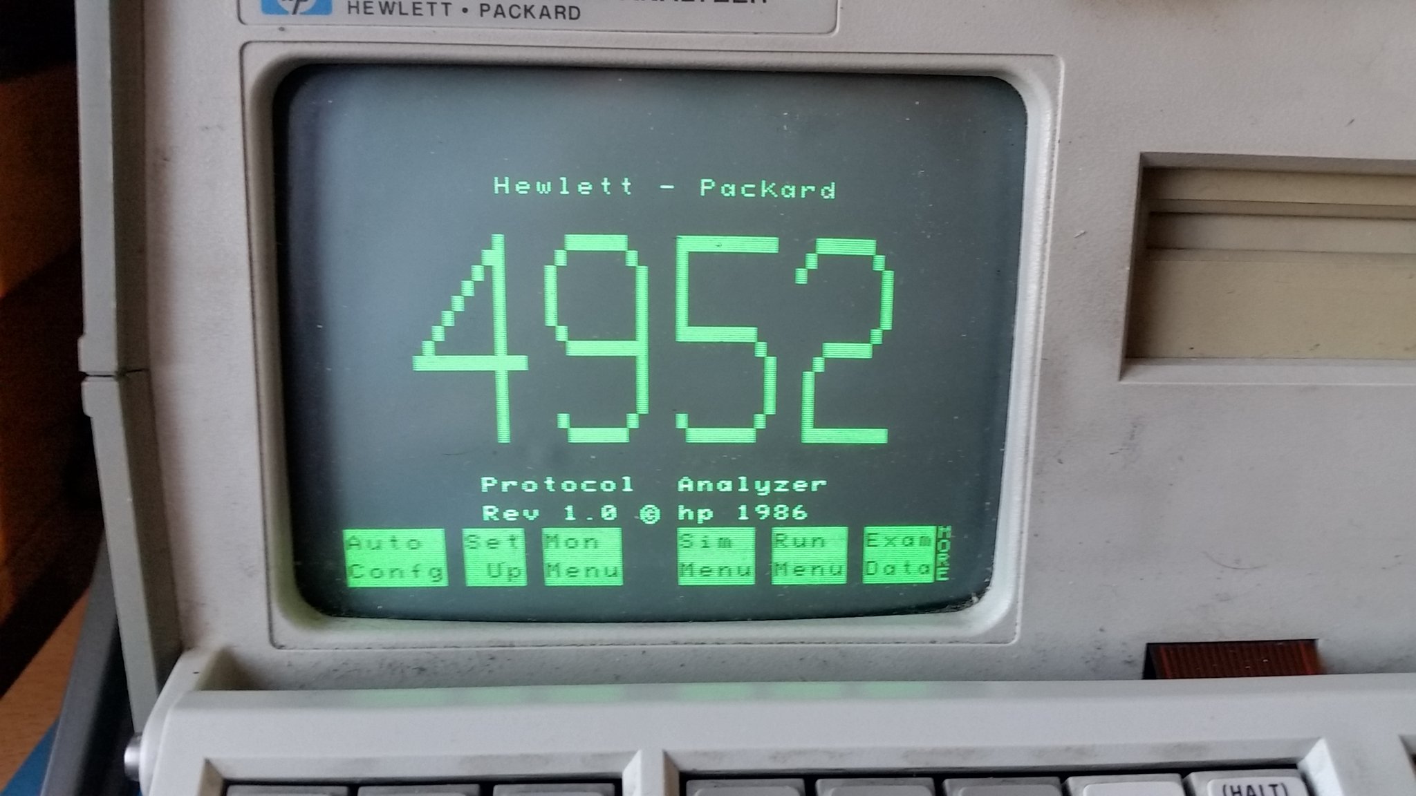
Fig. 1: A very dirty HP4952A. The screen is barely 10 cm wide, but it is very sharp and does not contain burn marks.
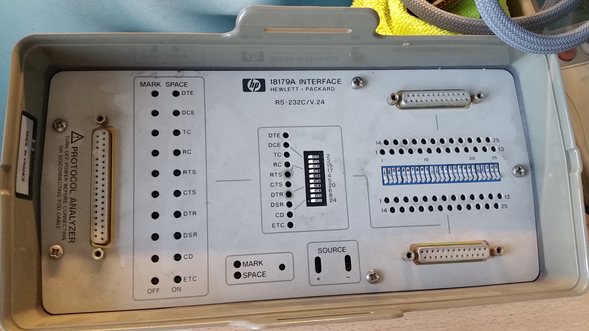
Fig. 2: A crusty HP18179A, an external pod that attaches itself to the HP4952A.
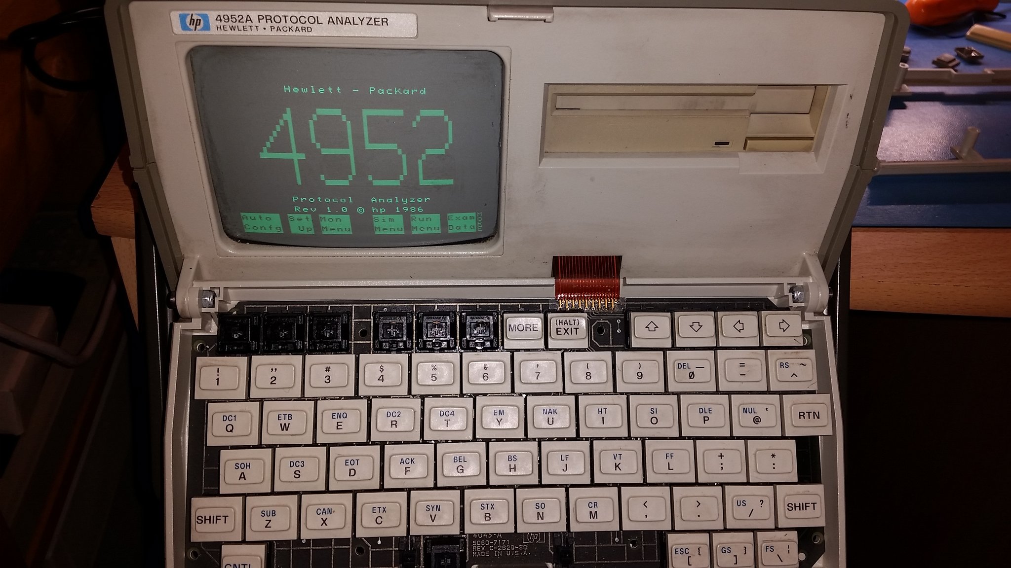
Fig. 3: Non functioning keys were fixed with contact cleaner.
Fixing the keyboard and tearing all apart
The keyboard of the HP4952A has a quite good feeling, is small and cute. Accessing to its circuit is easy, as there are a few self-tapping screws to remove on the back of it. Some contact cleaner fixed the two non-functioning soft-keys: it can penetrate along the shaft (easily accessible once the cap is removed, as shown in figure 3) to do its job.
By the way, the touch feeling is remarkable thanks to those switches: Cherry MX black. Nice to see that this vintage equipment comes well equipped! In 2020 those switches are still highly praised by lovers of mechanical keyboards. In fact, it seems that the whole keyboard comes from Cherry, as visible in figure 4, there is even the logo in the printed circuit board.
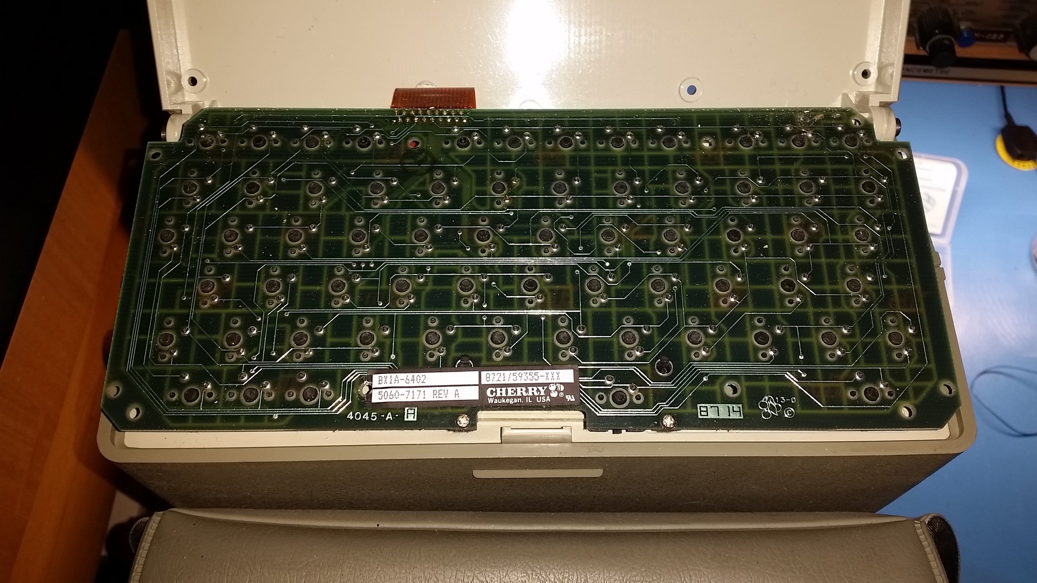
Fig. 4: The keyboard comes from Cherry and exploits their MX black switches.
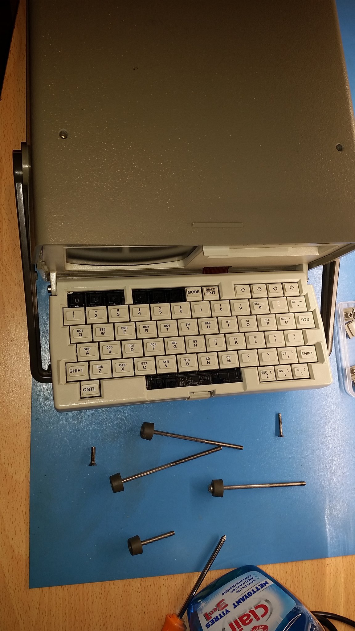
Fig. 5: After having removed the plastic case on top of the instrument, three long bolts plus a shorter one keep together the plastic case.
You should first remove the sort of soft plastic briefcase, attached to the top. As visible in figure 5, three long bolts keep together the instrument, the two at the back being slightly shorter. A fourth bolt is considerably shorter and is screwed in a peg attached to the disk drive chassis. I must confess that the three long bolts immediately made me think to the bolts keeping together a Rover K-series engine... The four bolts also keep in place the four rubber feet of the instrument.
It's not hard to tearing all apart, but one needs to be very careful at the CRT tube that can retain some charge after the instrument is switched off and that can implode if the neck is broken, shattering glass everywhere. Better leave it undisturbed!
Reaching the "pyro-capacitor"
Figure 6 shows the internals. In the purest classic HP tradition, they are a joy for the eye of an engineer (look for example here for other HP-awesomeness), albeit not reaching the incredible HP8640A signal generator.
As I said, there was a small explosion after a few minutes while I switched on the instrument. It is a very well known problem. The exploding X2 capacitor is a classic problem plaguing many electronic devices of the era with similar switching power supplies. A X2-class capacitor is used as a filter between the lead and the neutral of the mains, X2 meaning that it is designed to fail in a safe way as it is meant to be used for this function. Some of them (usually produced around mid-1980's) degrade to a point where they overheat and explode when power is applied, with a puff of smoke that leaves a characteristic persistent smell behind. This failure is so frequent that on social networks those capacitors are called "delayed smoke generators," "pyrotechnic capacitors", "pyro-capacitors" and things like that. Figure 7 and 8 show the capacitor still in the circuit and then desoldered, bearing the signs of the little explosion. Fortunately, it is very easy to source a modern replacement and I keep have some of them in my stock of electronic components.
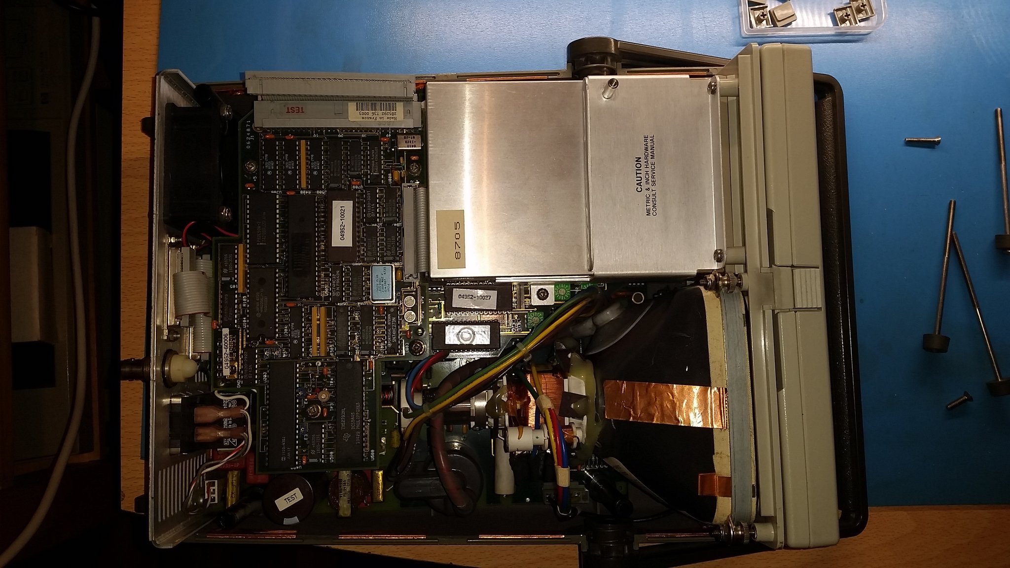
Fig. 6: The HP4952A internals.
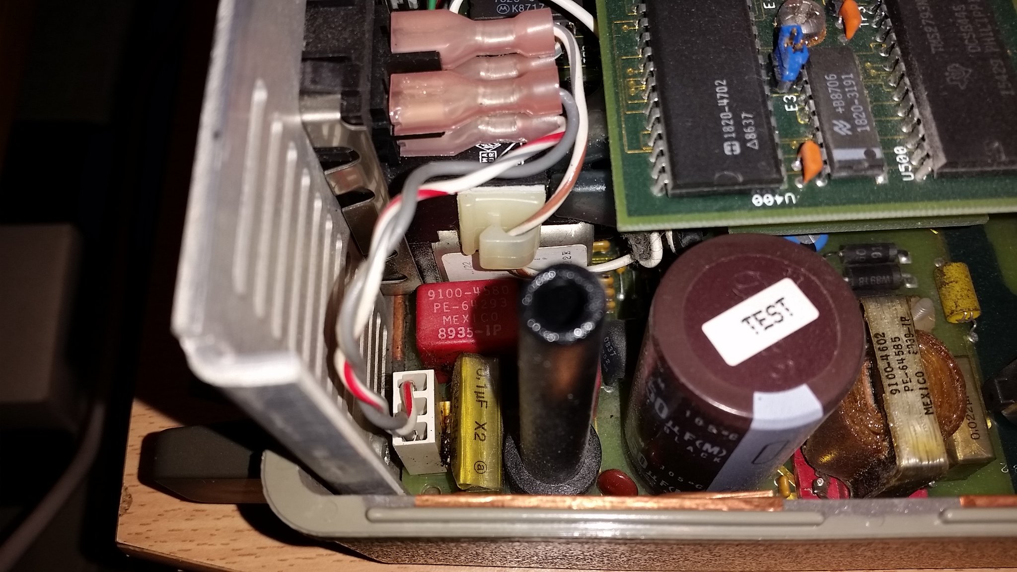
Fig. 7: An exploded X2 capacitor, among other things...
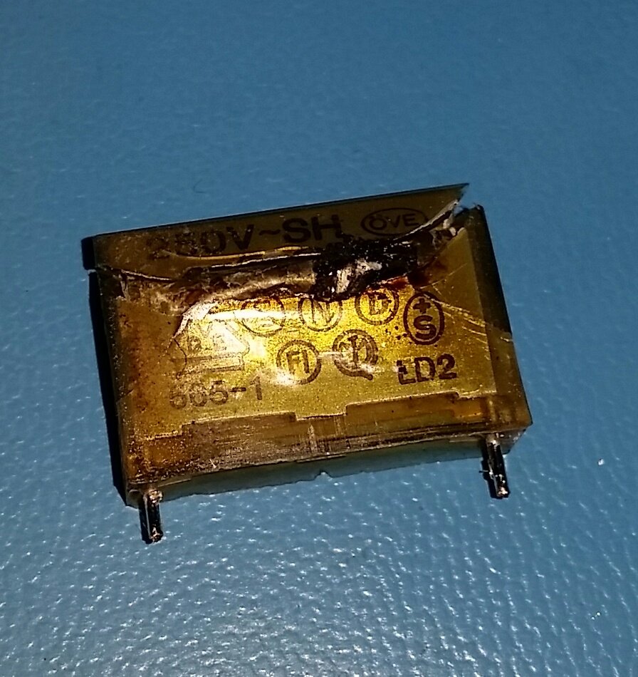
Fig. 8: A familiar sight, if you repair equipments from mid 1980's.
Other interesting things about the HP4952A
The HP4952A is a multi-processor system! Figure 9 shows an Intel 8088, placed on the board that controls the disk drive, a classic 16-bit processor of the x86 class, exploiting a 8-bit bus to save space and money in the package. On the larger board behind, there is a Motorola 68008, a wonderful 32-bit processor, again with a external 8-bit bus. Searching around, there is a Z80 processor on the main board and a 8051 microcontroller. This thing had some serious number crunching power in 1986! I am not sure that I want to know how much it cost at the time.
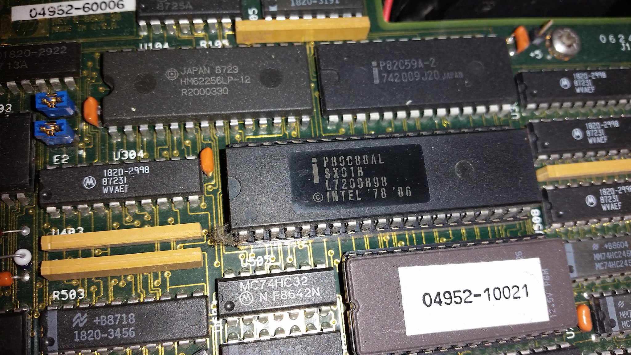
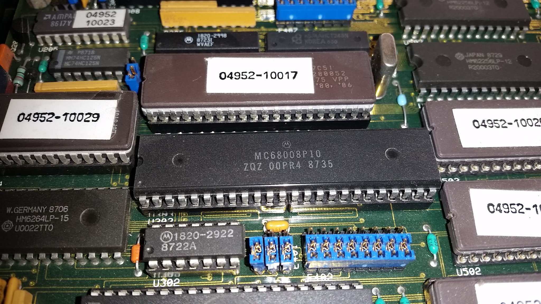
Fig. 9: This thing is complicated! A 8088 (top) and a 680008 (bottom) microprocessors, working together. There is a Z80 and a 8051 microcontroller, too!
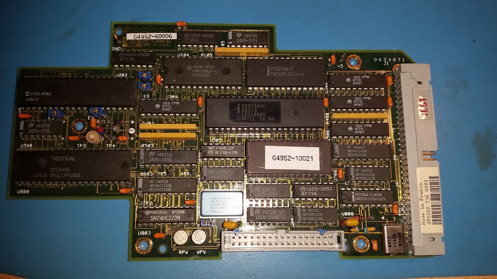
Fig. 10: The disk controller board.
Figure 10 shows the disk controller board, that sports the Intel 8088 processor. The "Made in France" label means that very probably this unit was assembled in a factory quite close from where I live. One can recognise a TMS2793 disk controller, a HM62256 static RAM (32KiB), a 82C59, a 82C59 interrupt controller, an EPROM containing the 8088 code and some glue logic chips.
The disk drive is a SONY MP-F52W-30, attached to the 34-pin connector in the bottom of the picture 10. Visible in figure 11, it required a good clean as it was covered with dust. I had to lubricate the insertion mechanism, as many times it could not latch the disks towards the spindle as it should. Apart from that, the disk drive operated correctly, as I could experience later.
The middle board (the one with the 68008 processor) contains a PCB-mounted 3.6V NiCd battery. Old batteries are a scary things in electronic circuits. They may leak chemicals, which can corrode the electronic circuits. In some extreme cases, they can even completely destroy a piece of hardware. Mine seems OK and the figure 12 shows that it is fully charged, providing almost 4V instead of 3.6V, but I will try to source a replacement anyway. In his very informative Twitter thread [2], Mark J. Blair suggests the Varta 55615703012 [3] as a drop-in alternative and I will probably see if I can source one at a sensible price in the future.
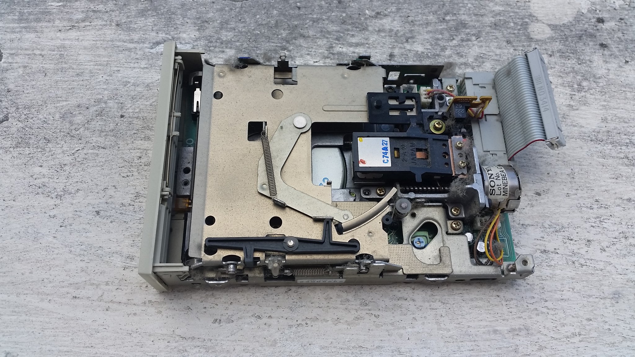
Fig. 11: A dusty SONY MP-F52W-30 3.5 inch disk drive (about 630 KiB).

Fig. 12: PCB-mounted Ni-Mh battery.
To complete the refurbishing work, I retro-brighted the space bar that was the only badly yellowed key and I left the plastic panel of the disk sunbathing for a few hours, to remove a yellow tint (fainter than the space bar). Of course, I cleaned the HP18179A pod, too, and all the cables.
One of the software side, it turned out that in the recent years several people investigated the instrument. In particular, David Kuder tried to understand something of the complex hardware architecture [4]. It appears that it is possible to write and execute Z80 programs on the machine and there is even modern software written for it. I was intrigued by Hugh Pyle's little "snek" game that I could successfully transfer on my HP4952A using his transfer Python routine. Everything is detailed on his GitHub project, where the source codes are available, too [5]. A screenshot of Snek is visible in figure 13, it is a "Snake" clone and it runs perfectly on my instrument. Other very useful information is made available by Thilo N. on the GitHub page [6] and on his Twitter thread [7].
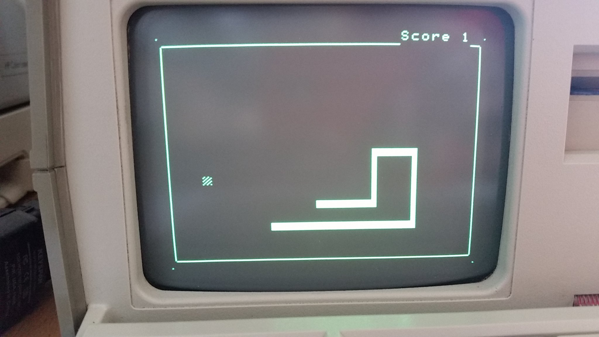
Fig. 13: Hugh Pyle's "Snek" game, running on my HP4952A.
Conclusion
This article describes the work done to refurbish an HP4952A protocol analyser.
I now have a spotless clean and perfectly working HP4952A, visible in figure 14. I used it to monitor the RS232 communication between my modern computer running macOS and my Olivetti M20 as visible in figure 15. I once developed some tools to transfer files on the M20 via the XMODEM and YMODEM protocols and I think I would have appreciated to have such a tool for troubleshooting my code!
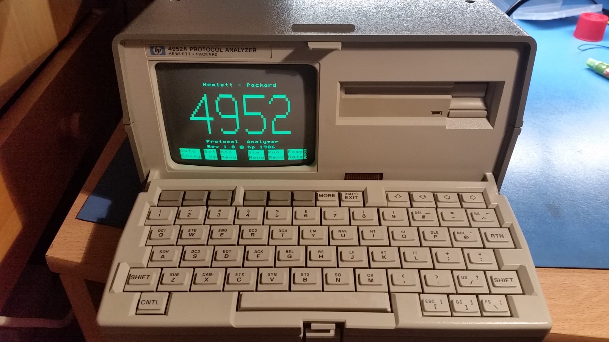
Fig. 14: A very clean and happy HP4952A.
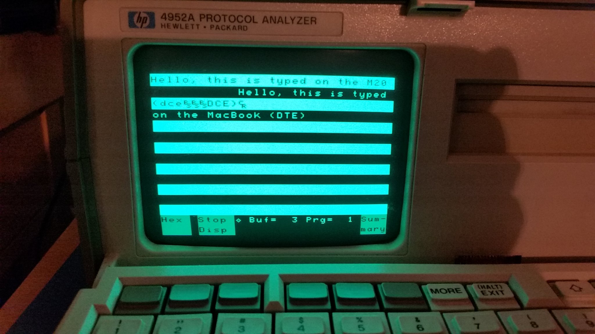
Fig. 15: The HP4952A monitoring a 9600 bps communication between a modern computer and an Olivetti M20.
Linkography
[1] - HP Museum HP4952A[2] - Mark J. Blair's Twitter thread (2018)
[3] - Varta 55615703012 NiMh batteries
[4] - David Kuder's Hackaday page about hacking the 4952
[5] - Hugh Pyle's GitHub project about the HP4952A
[6] - The content of HP4952A ROMs
[7] - Twitter thread by Thilo N.
Page log:
- December 30, 2022: corrected some typos and an error that prevented to access the page with a language that is not available.
- March 8th, 2020: first version of the page, in English.

Cet oeuvre est publié sous une Licence Creative Commons.